If you find this website useful, please check out my books or visit my Amazon Author page. Or even Buy Me a Coffee!
Electronics
Electronics
Across the internet there are plenty of threads discussing the poor circuitry for the DFrobot LCD Keypad Shield. This is an interface board that plugs into laregr Arduino boards to provide a 16x2 LCD and a set of control buttons.
The problem is that the backlight is controlled by a transistor and switched on by default by a resistor to +5v. The transistor's base is also connected directly to the D10 pin of the hosting Arduino.
This all works fine until you use the Arduino to try and control the brightness of the backlight. By default the pin is an input and so the resistor switches on the transistor and the display.
Make D10 and output and when it is LOW it over-rides the pull-up resistor and switches the backlight off.
If you make D10 high, the backlight comes on, but because the base of the transistor is now saturated it will take pretty much as much current from d10 as the pin can supply, overheating and potentially damaging the AVR microcontroller chip which is the heart of the Arduino. Not good.
Various solutions have been suggested but the easiest to get right and one that is totally effective is to put a 470R resistor between the D10 pin and the base of the transistor. This limits the current from D10 to about 10mA, which is still high for a control signal (enough to light an LED) but well within the chip's capabilities. Note that a 1K resistor won't be enough to switch off the backlight (it forms a potential divider with the existing pull up resistor).
The problem is knowing exactly where to fit this resistor, and what type to use. I used an 0603 surface mount resistor, but an 0804 which is a bit bigger and easier to handle with tweezers will fit (I just didn't have a 470R 0804 resistor).
This photo shows where the resistor fits, you have to cut the trace directly under it:
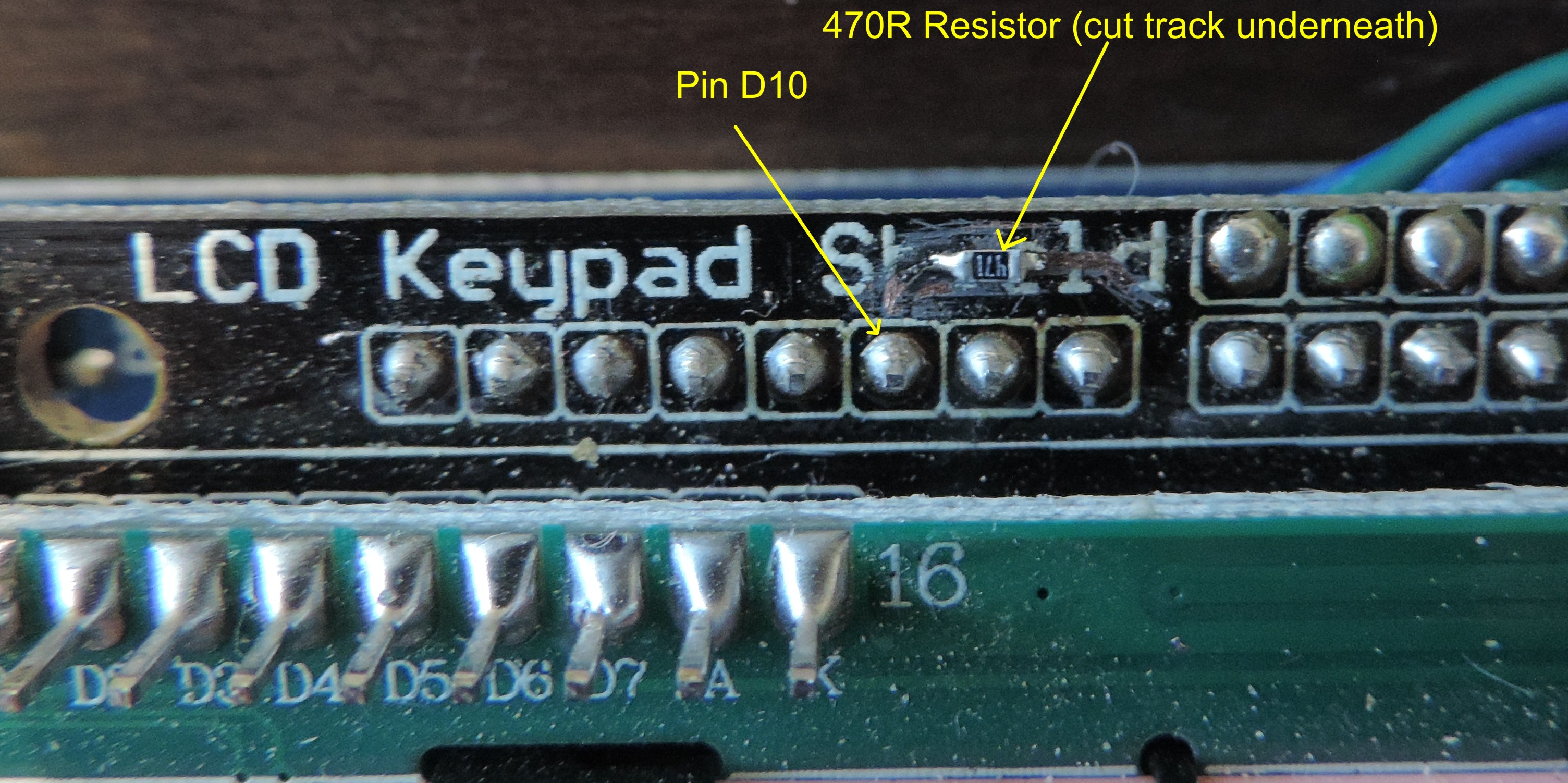
I use the tip of a scalpel blade to scratch off the lacquer on the trace from the D10 pin, then cut a tiny a gap in the copper (use a multimeter to check the gap is real!) With a small soldering iron tip I carefully tinned the trace either side of the gap then placed the resistor with precision tweezers. I am fortunate to have a proper rework station so I used a hot air gun (with minimum airflow) to reflow the solder and fix the resistor in place. If you have only a soldering iron, hold the resistor down with the end of the tweezers and hold the soldering iron tip against it until the solder flows. It can be done, I have made up whole SMT boards this way!
Check the resistor is properly connected and not shorted using a multimeter.
To control the backlight, you can incorporate this simple code snippit :
//Set up the brightness control:

#define backlight 10    //Pin D10

int brightness = 100; //Brightness can be anywhere from 0 to 255

pinMode(backlight,OUTPUT); //Sets the D10 pin as output - only do this after the resistor mod.

//To change brightness, alter its value as required then send it using this line:

analogWrite(backlight,brightness);
In practice this give really good results from full brightness to a completely dark display, and no overheating!
- Details
- Category: Electronics
BEEB Scope was a bit of fun with a relatively fast 8-bit DAC chip hung off the user port of a BBC Master Micro.
A really manky box (pics to follow, if I can find it) contained a front end with a suitable high impedance op-amp input.
The fast capture routine in the Beeb was about seven lines of 6502 code to continually read the input, allowing it to sample at about 220KHz (IIRC), which isn't bad for a 2MHz processor...

Beeb Scope screen grab
I never got round to making a really decent interface, but as I was between scopes it actually got me out of a hole a few times! A couple more screen grabs, not Compaq 5 1/4" floppies and genuine CUB monitor! This stuff belongs in a museum, not the loft.

Beeb Scope does a nice job of capturing a pulse.

Is there nothing BEEB Scope can't do?
- Details
- Category: Electronics
A 1/4 VGA Colour Display Driver Using BBC Micro VDU Codes
The display driver uses the equivalent of standard BBC Microcomputer VDU codes, however, because the display is 65kB colour, with a fixed resolution, there are differences.

The Display in Action
The driver is written to operate from a bi-directional eight-bit data stream. It will operate from a unidirectional stream, but in this case the display cannot be interrogated. The data stream was originally chosen as RS232 for convenience in development using a simple terminal programme on a PC, but the code easily adapts to any AVR serial interface including any UART or USART mode, SPI (the intended end use) and two wire interface (I2C compatible). Any bespoke serial or parallel transmission system that can generate either an interrupt or a subroutine call on receipt of a valid data byte can be used.
All extra bytes must be sent, even if zero. These extra bytes will not cause any VDU actions to take place, but if not sent unpredictable results can be anticipated.
|
DEC |
HEX |
ACTION |
EXTRA BYTES |
DESCRIPTION |
|
0 |
00 |
Null |
0 |
Does nothing but take a short period of time. Send a null to receive a byte without causing side effects when using SPI. |
|
2 |
02 |
(Enable printer) |
|
|
|
3 |
03 |
(Disable printer) |
|
|
|
4 |
4 |
Text at text cursor |
0 |
Write text at the text cursor in the text window (default behaviour). |
|
5 |
5 |
Text at graphic cursor |
0 |
Write at the graphic cursor. The top left pixel of the character is at the graphic cursor so text may be positioned anywhere in this mode. If the graphic cursor is outside any graphic window text may not be visible. The cursor advances by one character after writing, and wraps around (it does not scroll if it goes off the bottom, but wraps to the top). |
|
6 |
06 |
Display on |
0 |
If the display has been disabled with VDU21, this command switches it back on again. |
|
7 |
07 |
(Bell) |
|
Produces a beep |
|
8 |
08 |
Backspace |
0 |
Move the cursor left one character space (if off screen causes a wrap to end of next line, scrolling if required). |
|
9 |
09 |
Horizontal Tab |
0 |
Move the cursor right one character space (if off screen causes a wrap to beginning of next line, scrolling if required). |
|
10 |
0A |
Line Feed |
0 |
Move the cursor down one line (if off screen causes a scroll). |
|
11 |
0B |
Vertical Tab |
0 |
Move the cursor up one line (if off screen causes a downwards scroll). |
|
12 |
0C |
Form Feed |
0 |
Clears the text area and home the cursor to top left (if a text window is in effect only the windowed area is cleared). |
|
13 |
0D |
Carriage Return |
0 |
Move the cursor to the left of the current line. |
|
14 |
0E |
(PAGE MODE ON) |
|
|
|
15 |
0F |
(PAGE MODE OFF) |
|
|
|
16 |
10 |
Clear graphics window |
|
Clears the current graphics window to the current graphics background colour. |
|
17 |
11 |
Text Colour |
3(1) |
Sets the text colour. See Text Colours. |
|
18 |
12 |
Graphics Colour |
4(2) |
Sets colours used for graphic plotting and defines default plot action. See Graphics Colours. |
|
19 |
13 |
Upload Bitmap |
1024 |
Uploads a full screen bitmap image. See Uploading Full Screen Bitmaps. Change to X,Y,width,height,data |
|
20 |
14 |
Default colours |
0 |
Restores default colours. |
|
21 |
15 |
Display Off |
0 |
Turns off the display, all commands still take a full quota of extra bytes and may be forwarded to the printer/RS232. |
|
22 |
16 |
Mode |
1 |
Selects the display mode. See Screen Modes. |
|
23 |
17 |
Define Characters |
9 |
Allows the definition of user-defined characters with codes 224 to 255. Codes 31 and below and 135 to 221 are reserved for display control purposes (see below) and expansion. Due to SRAM limitations of the MEGA16, redefinition of codes 32 to 126 is not implemented. See Character Bitmaps. |
|
24 |
18 |
Define Graphic Window |
8 |
Creates a graphic window. The four byte-pairs (low byte first) represent left, bottom, right and top columns and lines of the window respectively in graphic units. This command is range checked and out of scope ordinates are set to the appropriate minimum or maximum. |
|
25 |
19 |
Plot commands |
5 |
Implements a graphics plotting action. First extra byte is action, next two byte pairs define ‘new co-ordinate’ (low byte first), the previous two pairs represent the ‘current’ and ‘old’ co-ordinates respectively. Points outside the graphic window are not plotted, but the cursor positions are updated anyway. See Plot Commands. |
|
26 |
1A |
Restore default windows |
0 |
Restores the default text and graphics windows without otherwise affecting the display. |
|
27 |
1B |
Escape |
3 |
Allows the sending of *FX or ‘osbyte’ control codes. The three extra bytes represent A,X and Y in the command *FX A,X,Y. All commands return a single byte result. If the command is unknown the result is the command number. See *FX or OSBYTE Commands. |
|
28 |
1C |
Define text window |
4 |
Creates a text window. The four bytes represent left, bottom, right and top columns and lines of the window respectively Use VDU26 rather than redefining a full window with VDU28. This command is range checked and abandoned if out of range. |
|
29 |
1D |
Define graphics origin |
4 |
Sets the graphic origin according to the two byte-pairs (low byte first) in graphic units. |
|
30 |
1E |
Home |
0 |
Homes the text cursor to the top left of the screen. |
|
31 |
1F |
Tab |
2 |
Moves the text cursor to the co-ordinates X,Y. This command is range checked. |
|
127 |
7F |
Delete |
0 |
Implements a backspace and clears the current character cell. |
Note: In ‘text at graphic cursor mode’ codes 8-11 do not generate a scroll off the top or bottom of the screen, instead the cursor wraps to the top or bottom as appropriate.
Text Colours
Text colours are sent in the formal R:G:B one pixel but only the bottom 5 bytes (i.e. MOD32) are used. If the top bit of the first byte (red) is set, then the text background colour is changed.Screen Modes
Because of the limitations of the LCD screen (fixed resolution) changing mode only affects the text size displayed. Characters are 8 lines high in all modes.
|
MODE |
TEXT |
GRAPHICS |
|
0,3 |
80 characters wide (4 by 8 grid) |
128 x 64 Pixels, 2044 x1024 Graphic Units |
|
1,4,6 |
40 characters wide (8 by 8 grid) |
128 x 64 Pixels, 2044 x1024 Graphic Units |
|
2,5 |
20 characters wide (16 by 8 grid) |
128 x 64 Pixels, 2044 x1024 Graphic Units |
|
7 |
Reserved for expansion |
128 x 64 Pixels, 2044 x1024 Graphic Units |
Graphics may be plotted in all modes, to single pixel resolution.
Different sizes of character may be mixed using the following sequences:
VDU 27, 184, 0, 255 returns the character width.
VDU 27, 184, X, 0 sets the character width to X. Values other than 4, 8 or 16 are invalid.
Note that if a character wider than the remaining line space is plotted, the character will wrap around the screen.
Graphics Units
The LCD screen does not have the same proportions as the original BBC modes (up to 640 pixels wide, always 256 pixels high), it is always 320 pixels wide by 240 high. The size of a BBC screen in ‘graphics units’ was 1280 by 1024. Pixel sizes varies from 2 to 8 graphics units wide and always 4 high. The LCD screen size has been fixed at 1280 by 960 graphics units. This means that 1 pixel is 4 by 4 graphics units in size regardless of mode.
Graphics Colours
These are set using VDU18 followed by four extra bytes.
Byte 1 has the following meanings:
Byte 1 |
ACTION |
|
0 |
Plot the colour specified |
|
1 |
OR the specified colour with that already there. |
|
2 |
AND the specified colour with that already. |
|
3 |
EOR the specified colour with that already there. |
|
4 |
Invert the colour already there. |
|
>4 |
Out of range, command ignored. |
If byte 2 is less than 128, then odd numbers give foreground black, even give foreground clear.
If byte 2 is 128 - 255, then odd numbers give background black, even give background clear.
Many plot commands override the current graphics colours.
Uploading Full Screen Bitmaps
Character Bitmaps
All characters are defined on a 8x8 pixel grid. Because of the way the LCD screen is bitmapped, these are defined in columns left to right, with the top pixel of each column having the value 0 and the bottom pixel the value 127. This is rotated with respect to the original BBC characters because of the way the LCD screen memory is addressed. In practice this should only affect defining characters.
In modes 1,4 and 6 one character pixel maps to one screen pixel. In modes 0 and 3 the four leftmost columns of a character are displayed. In modes 2 and 5 each character pixel maps to two screen pixels.
The BBC Basic for Windows program AVR Chardes is a utility that allows on-screen editing of character definitions and produces a file including a text listing of these definitions.
*FX or Osbyte Commands
These are three-byte commands for controlling or finding information on a range of operating system variables. They are sent using the VDU27 command sequence:
VDU 27, <command number>, X, Y
The commands return a result, usually a single byte, sometimes more. If the command is unknown the result is the command number. Some commands can be used to read or write a system variable, in these cases the operation performed is:
<new value> = (old value AND Y) EOR X
The new value is returned. By setting Y=255 and X=0 the system value can be read without changing it. By setting Y=0, X can be used to write any desired value. The ingenious may use bitmasks in Y and X to write or toggle individual bits.
|
DEC |
HEX |
ACTION |
DESCRIPTION |
|
0 |
0 |
Break/Display O/S version |
If X=0 this resets the I/O driver and displays the O/S version. If X=1 this returns the OS version. |
|
19 |
13 |
Display Brightness |
Reads or writes the display brightness |
|
25 |
19 |
Choose font |
Sets font: X=0 – Default MyFont X=1 – BBC Font X=2 – Arial X=3 – Arial Bold |
|
117 |
75 |
Read VDU status byte |
Returns single byte with each bit having the following meaning: 0 set when cursor visible 1 set when a scroll is pending 2 set when a text window in force 3 set when in paged mode 4 set when in printer to RS232 mode 5 set when VDU drivers disabled 6 set when in graphics cursor mode 7 set when plotting dotted lines These are different meanings to those returned in BASIC IV. |
|
|
|
|
|
|
|
|
|
|
|
134 |
86 |
Read text cursor position |
Returns the X and Y co-ordinates of the text cursor as single bytes in that order. |
|
135 |
87 |
Read character at cursor and screen mode |
Returns the code for the character at the cursor, or zero if the character is not recognised. All system and user defined characters are recognised. The number of the current screen mode follows. |
|
144 |
90 |
Screen start line |
Reads or changes the display start line. Unlike the BASIC IV any changes are effective immediately. Value is a signed byte. Default is 0. |
|
154 |
9A |
Read or write cursor appearance |
Reads or changes the cursor pattern byte. The default of &80 is a single line at the bottom of the character cell. |
|
155 |
9B |
Read graphic palette |
Returns the current graphics foreground and background graphic colours. |
|
161 |
A1 |
Read from user EEPROM |
X = EEPROM location, value of byte is returned. |
|
162 |
A2 |
Write to user EEPROM |
X = EEPROM location, Y = value of byte to be written. No value returned. Data written in this way is preserved even through a complete power down. |
|
184 |
B8 |
Read or write character size |
Reads or changes current character width, independent of mode setting. Use with care as changing to character size may cause unpredictable effects if they ‘wrap’ at the end of lines. (New function). |
|
217 |
D9 |
Page line count |
Reads or changes the line count at which scrolling stalls for page mode (default is 6) |
|
241 |
F1 |
User Flag |
Reads or changes the user flag. This is useful as a location that is unchanged by any other action, aside from a complete power down. |
User EEPROM
There is a whole page of user EEPROM (256 bytes) in the display driver. This can be used for any purpose. This can be read using:
VDU 27, 161, X, Y
Where X is the byte to read and Y is not significant, it may be written using:
VDU 27, 162, X, Y
Where X is the byte to write and Y is the value to write.
Plot Commands
Plot commands all have the format:
VDU 25, P, X; Y;
Where P is the action required, X and Y are two-byte co-ordinates (signed integers, low byte first) in external co-ordinates relative to the graphics origin. Each action has eight implementations, determined by P MOD 8. These are:
P MOD 8 |
Implementation |
|
0 |
Fast relative move i.e. the new co-ordinates are added to the old co-ordinates. |
|
1 |
Relative plot in current foreground colour and action as defined by VDU18. |
|
2 |
Relative plot inverting the colour already there. |
|
3 |
Relative plot in current background colour and action as defined by VDU18. |
|
4 |
Absolute move i.e. the new co-ordinates replace the old co-ordinates. |
|
5 |
Absolute plot in current foreground colour and action as defined by VDU18. |
|
6 |
Absolute plot inverting the colour already there. |
|
7 |
Absolute plot in current background colour and action as defined by VDU18. |
New and current (but not old) co-ordinates are stored in external units to avoid cumulative errors with repeated relative moves, though all plotting is done after conversion to internal units.
|
DEC |
ACTION |
DESCRIPTION |
|
0-7 |
Plot line |
Both end pixels are plotted |
|
8-15 |
Plot line |
Final pixel omitted |
|
16-23 |
Plot dotted line |
Both end pixels are plotted |
|
24-31 |
Plot dotted line |
Final pixel omitted |
|
32-39 |
Plot line |
First pixel omitted |
|
40-47 |
Plot line |
Both end pixels are omitted |
|
48-55 |
Plot dotted line |
First pixel omitted |
|
56-63 |
Plot dotted line |
Both end pixels are omitted |
|
64-71 |
Plot a point |
A single pixel is plotted |
|
|
|
|
|
80-87 |
Plot filled triangle |
A filled triangle is drawn with vertices at the old, current and new co-ordinates. |
|
96-103 |
Plot filled rectangle |
A filled axis-aligned rectangle is drawn with the new and current co-ordinates at opposite corners. |
|
|
|
|
|
144-151 |
Plot circle outline |
A circle is drawn centred on the current co-ordinates with radius equal to the difference between the new and current y-co-ordinate, i.e. VDU 25,145,X;Y; draws a circle of radius Y at the current co-ordinates.* |
|
152-159 |
Plot filled circle |
A filled circle is drawn centred on the current co-ordinates with radius equal to the difference between the new and current y-co-ordinate, i.e. VDU 25,153,X;Y; draws a filled circle of radius Y at the current co-ordinates.* |
|
160-167 |
Move rectangle |
The rectangle defined by the old and current co-ordinates is moved to the new co-ordinates and replaced by a blank background rectangle |
|
168-175 |
Copy rectangle |
The rectangle defined by the old and current co-ordinates is copied to the new co-ordinates |
*This implementation is slightly different from BASIC IV, where the new co-ordinates designate a point on the circumference of the circle.
- Details
- Category: Electronics