Over recent years various 3 1/2” centre height “mini-lathes” have become increasingly popular as an entry-point into model engineering. Personally, I don’t like the term ‘mini lathe’ – it suggests that they are toy-like or unsuited to ‘real model engineering’. Fifty or sixty years ago, if you could not afford a large, full-featured lathe one choice you had was a true lathe such as the Adept, Flexspeed or Centrix Micro – each of which could truly be described as ‘mini’ and lacked any screwcutting capability. Even so these lathes were capable of producing superb results in the right hands, and in the hands of some owners were modified to become full featured and true precision instruments.
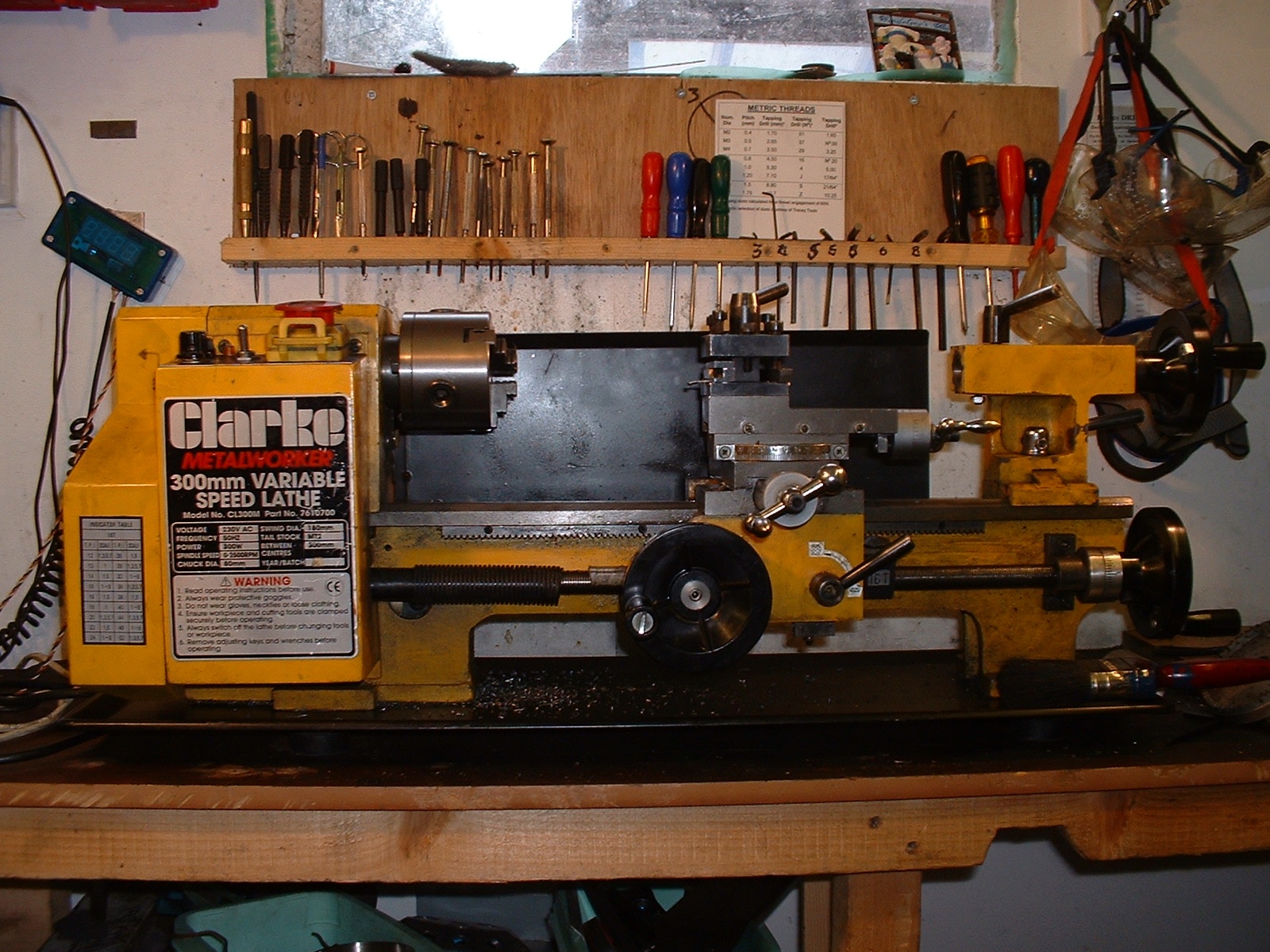
My mini lathe, a Clarke CL300M, taken before the bearing change. At least eight other modifications can be seen in this view!
The modern ‘mini-lathe’ is technically far advanced from these historic examples, though it fills the same niche. It has much greater capacity, a built in variable-speed motor, screwcutting and fine feed, is far more rigid and, with the benefit of modern mass production, is probably more accurate. The one issue that does get raised by users of these lathes, however, is difficulty in parting off. Parting is one of the most demanding tasks for any lathe, as it involves taking a broad cut with an overhung tool, often at the bottom of a deep groove.
You may ask what all this has to do with roller bearings and angular contact? Well there are several requirements for successful parting, and the quality and adjustment of the lathe mandrel bearings are one. Mini lathes are supplied with the mandrel fitted with ball bearings as standard, and for some users these have proven to be a source of trouble when parting off or even, in extreme cases, when trying to achieve good surface finishes. In lathes where these bearings are not up to scratch, changing to roller bearings is an economic and realistic way to address the problem.
See also: Changing the Bearings on a Mini Lathe
But there are many other pitfalls for the careless parter-offer, and unless these are addressed changing your mandrel bearings is pointless, and if they are, you may not find the need to change them anyway. So in this article (sorry!) I will explore the mysteries of parting off and explore the various solutions to allowing our mandrels to rotate.
Perhaps every model engineer wishes to attain LBSC’s nirvana of ‘parting steel with a sound like frying bacon’, but it was the greatly respected George Thomas who made parting off a fine art. He combined a well-adjusted lathe, a rear toolpost, the right tool and the right speed. With a special tool shape he reached a point where he could part off 1 1/2” mild steel at 615 rpm! By his own admission this was a piece of showmanship reserved for exhibitions, and more usually he found a suitable speed (for mild steel) of 200 rpm per inch of diameter.
A well adjusted lathe means ensuring the saddle, cross-slide and top slide all move smoothly, but without any trace of shake or movement. Rock the toolpost and watch anywhere two slides rub together – if you see a bead of oil moving in and out, then they are probably too loose. Make sure there is no play in the mandrel in its bearings. If there is, cautiously tighten the locknuts at the rear of the mandrel.
A rear toolpost, with upside down tool, is widely recognised as improving parting off, by reducing the chance of ‘digging in’. Apparently the rear-mounted tool will tend to spring out of, not into, the work and for materials which produce short chips, rather than curls of swarf, these will tend to fall clear of the cut. I have never seen a completely convincing explanation of the geometry involved, but several respected model engineers have testified to the effectiveness of this approach, and it has been a popular technique since the 1940’s. Mini-lathes do not mount chucks on a screwed mandrel nose and have reversing at the flick of a switch. This means to explore the benefits of this geometry one simply has to invert and pack up a parting tool in the normal toolpost, and reverse the lathe rotation.
George Thomas’ ideal tool had a v-groove on top and the end ground to a v-point, to encourage the formation of curled, narrow swarf (Duplex advised a rounded convex-ended tool for the same reason). I’m sure that both would have admitted that this is a counsel of perfection and that what really matters is a sharp tool with appropriate top rake and adequate front and side clearance. Two essential pieces of George Thomas’ advice, however, are to match the size of the tool to the job and to keep the end of the tool square to the job. Small tools are not rigid enough to tackle large diameters and the angled tool end that avoids making an end pip produces sideways forces that can bend the tool off line and jam the job.
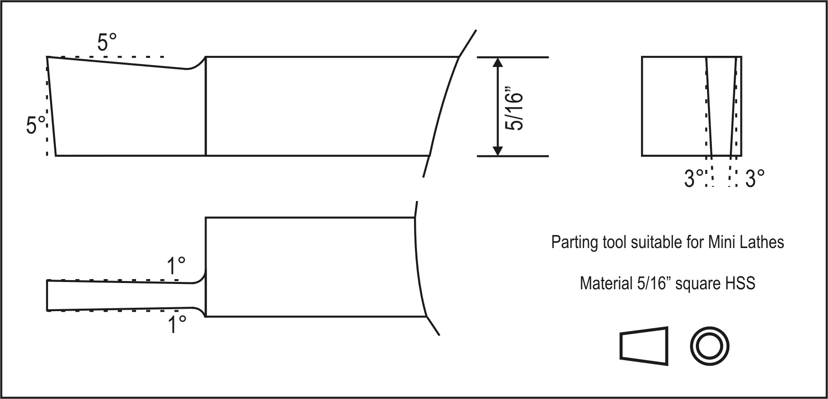
This drawing shows ideal angles for a normal parting tool as recommended by Duplex.
Getting the right speed for any parting job depends on so many variables (the material, its diameter, the tool and the state of the lathe, and some would say the phase of the moon) that there has to be an element of trial and error. The same applies to getting the correct rate to feed in the tool. Fortunately the variable speed control of mini lathes comes into its own for parting – you can gently vary the speed to get the best results, and also speed up as the diameter drops.
Finally, don’t be afraid of the job. A jam up and a broken tool-tip can make you understandably cautious. George Thomas was adamant that a confident and positive approach was essential, and that over-cautious pecking at the work will never bring good results. Don’t just watch either – let your ears and your fingertips tell you what is happening.
A 1940’s article by LBSC advocated a useful tool, not for parting off, but for the similar task of making deep, wide grooves in large diameters. The tool has the shape of a fish’s tail in plan view, the opposite of George Thomas’ tool. I ground a shallow vee in the end of a normal parting tool using a mini drill mounted stone, in order to turn a wide groove in 3” diameter cast iron. I found this shape of cutter was less liable to chatter than a normal parting tool. In use it is fed in five to ten thou at one side of the groove, moved across to the other side of the groove and fed in again before the return journey. The ‘double pronged’ design cuts the full width of the slot to the full depth with ease.
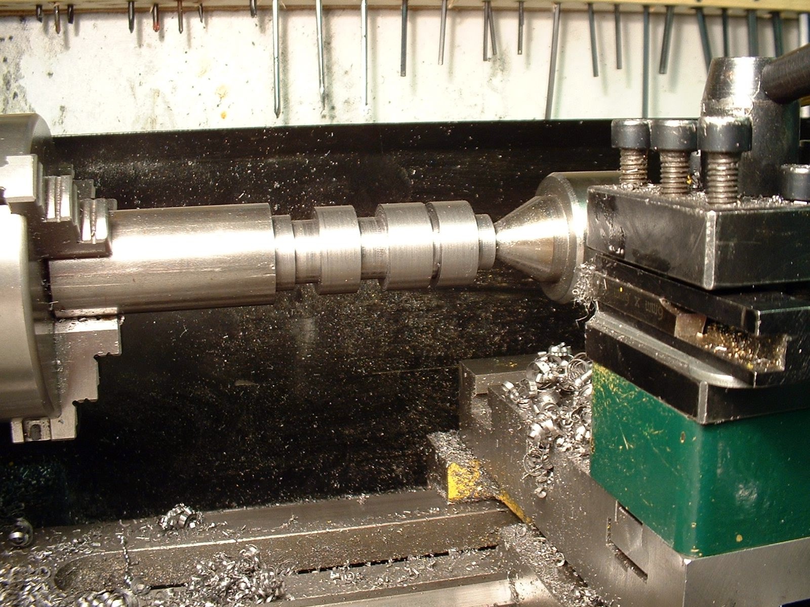
Producing a series of gear blanks in a medium-tensile steel was essentially a multiple parting off operation. Note chatter marks at the bottom of some diameters.
At first I had all the parting off problems recounted by many mini-lathe owners, and had my fair share of ‘dig ins’ and chatter. In time I was able to overcome these by following the above advice. I also found the huge difference made by a brush full of neat cutting oil in the groove. Most of all, I found the benefit of having confidence to feed in and get a positive cut. After a fair share of jams and scrappers, I eventually reached the point where I could reliably part off 1 1/8” alloy steel. With standard bearings I even used a parting tool to cut a deep groove in some (freely machining) 2 1/4” diameter cast iron.
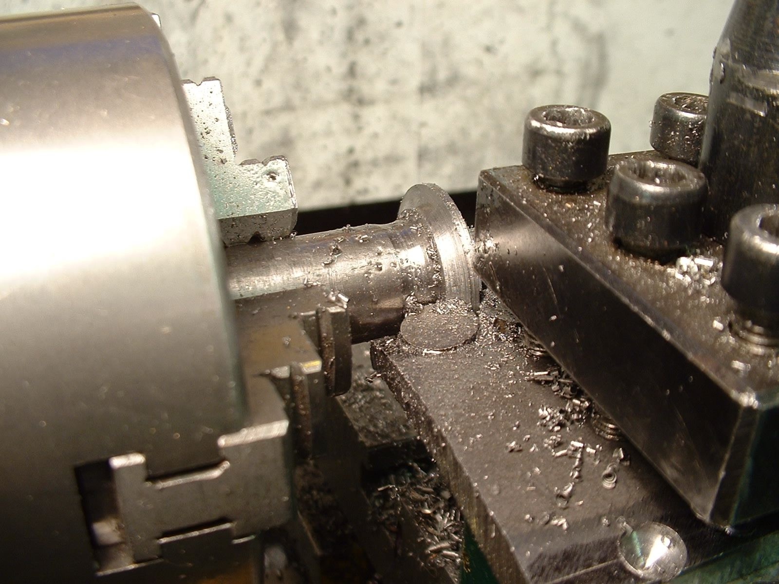
Using a broad form tool, such as when making a gear cutter in silver steel, is possibly one of the few tasks even more demanding than parting off.
Let us assume that you are in the position of some mini-lathe owners, having tried every tip and wrinkle and still not getting successful parting off. The final option is to replace the mandrel bearings in the headstock. There are a number of requirements for lathe bearings. They need concentric accuracy, they must be able to take both high axial loads and thrust loads, they must have low friction and ideally they must have a long life.
Roller bearings are the ideal choice when turning the barrels of a battleship’s 16” guns, simply because of the loads involved, but for small lathes the choice is less clear as almost any type of bearing could be used. Once, many had mandrels running in a plain cast-iron headstock, which is a perfectly good solution with adequate lubrication. Before the Second World War plain and taper bushes and sometimes ball bearings were the rule. Roller bearings were scarce during the first half of the twentieth century, but their use took off during the Second World War. Even so many top quality post-war lathes, notably Myford’s ML7, used plain bushed bearings and a ball thrust bearing, whilst the Super 7 used a hand scraped tapered bronze bush at the head of the mandrel. There is no doubt that these bearings could handle any task within their lathe’s capacity. On the other hand slightly larger lathes, such as those by Boxford and Colchester, typically had roller bearings.

The mandrel of a Milnes Type R lathe, fitted with two taper roller bearings at the front of the mandrel and two further ordinary roller bearings.
At a slightly earlier time LBSC was in no doubt – anything but roller bearings! In one of his “Lobby Chats” he told the tale of new “Type R” lathe he had received in 1923 from Henry Milnes, of Bradford, to replace his 3 1/2” Drummond. If I dare paraphrase a tale he told in his inimitable fashion, it went something like this: He didn’t care for the specified roller bearings, but obtained a written guarantee that, if unsatisfactory, they would be replaced with plain ones. Within three weeks he had detected ‘fine lines” and got onto the maker, who replaced the front bearing with a bronze cone. Another three weeks and the problem arose again, and this time it was agreed to be the fault of the tail-end roller bearing. The patient Mr Milne agreed to supply a specially made roller bearing, but there would be a few weeks delay. Now LBSC depended on his lathe for his living, so the manufacturer sent him a temporary bronze bush, which he fitted, immediately curing the trouble. In due course the new ball bearing arrived, but as the bush was doing fine, he thought he’d keep it for the time being. Some time later, while turning a wheel for ‘Bantam Cock’ on the self-same lathe he started getting chatter marks; inspection revealed a little play in the bronze bush, it had worn just slightly oval. The replacement ball bearings were found to be a perfect fit. The bush was put into ‘honourable retirement’, with due reverence. This story was told in 1946 – the temporary fix had done its duty for over twenty-three years.
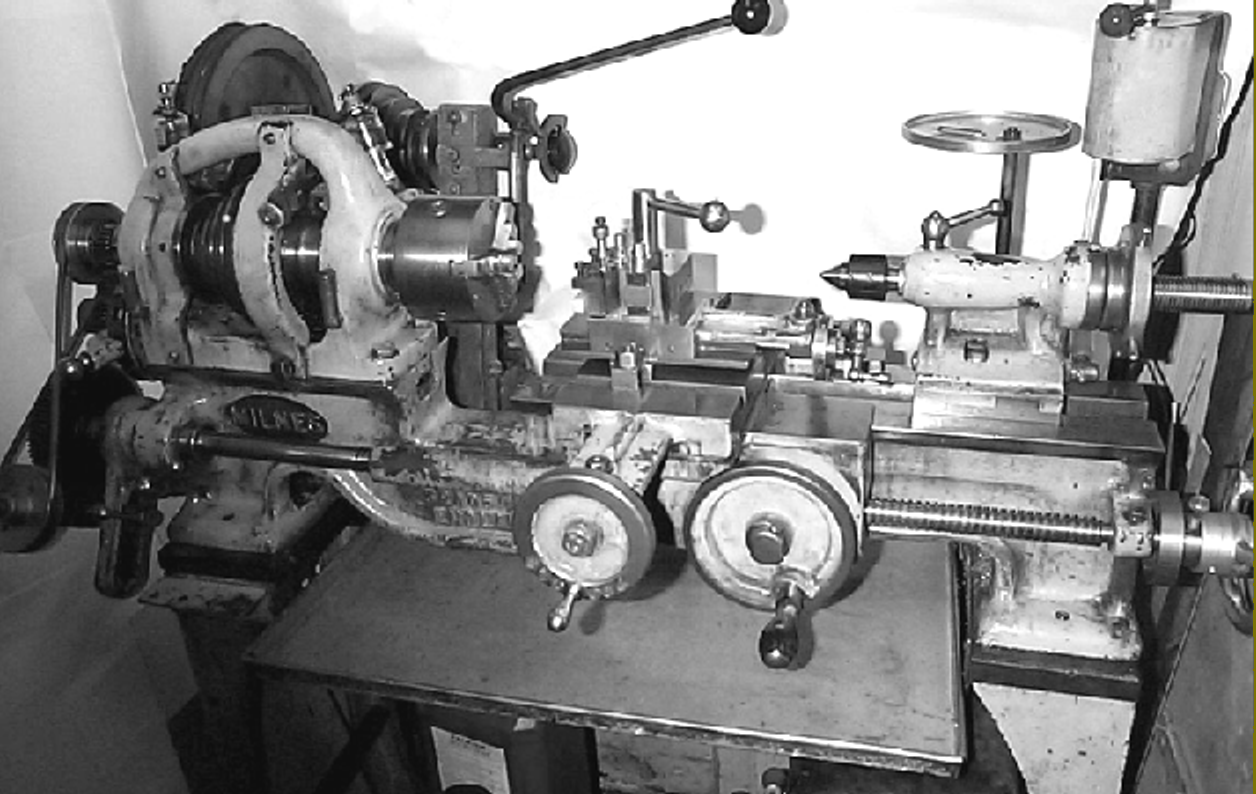
A Milnes Type-R 3 3/4” lathe, fitted with lubricators for the mandrel bearings, as used by LBSC for around a quarter of a century (see www.lathes.co.uk for more details of this and other veteran lathes).
So Curly wouldn’t touch a roller bearing with a barge pole, but a year later in 1947 they were stoutly defended in the Editor’s correspondence. E. H. Doughty, British Timken Ltd.’s Chief Technical Engineer, challenged some of the magzine’s responses to queries concerning the rigidity and finish achievable with roller bearings earlier in 1947. The detailed letter included arrangements for four-, three- and two-bearing spindles. The two-bearing arrangement is exactly the type that applies to mini-lathes, and is stated to be ideal for smaller lathes where temperature variations are small. He claimed high precision, robustness, long life, low friction and the potential for high speeds as the benefits of their bearings. Mr Doughty did not agree that plain bearings were preferred by most users, claiming that the use of roller bearings was increasing rapidly both before and after the Second World War. He added that during the war tens of thousands of units gave “every satisfaction” in machine tools of all kinds.
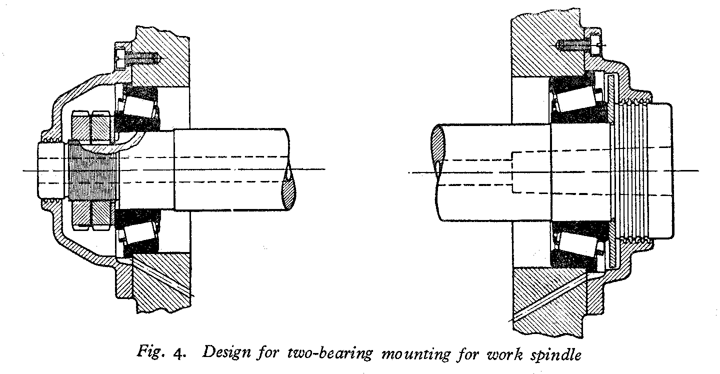
This design for a two-bearing work spindle by British Timken is comparable with that applying to mini lathes.
Another advantage of ball or roller bearings is ease of lubrication. A plain bearing mandrel demands a slow but uninterrupted flow of oil, otherwise rapid wear will soon be apparent. A sealed ball bearing may not expect any lubrication during its normal service life, and even ‘open’ grease-packed bearings need only occasional attention (how often do you repack the axle bearings on your family car?)
Now Curly’s problem was not just chatter, it was also fine surface patterns on the work. Unsatisfactory finish was clearly a concern among likely users of roller bearings. Mr Doughty claimed very fine finishes, even at high production rates. Perhaps a clue to where poor finishes arose is given by his explanation of the need for no or minimal preload. Apparently the popular impression was that a fair degree of preload was necessary, generating excessive friction. I imagine the ‘wedging’ action of taper roller bearings makes them easier to overtighten than angular contact ball bearings, and that one symptom of this might be a poor finish. Another one-time Timken employee - ME Technical Editor, Neil Read, pointed out that in 1923 LBSC’s roller bearings would have been made to standards of fit and finish far from what we might expect today.
Whilst there is no doubt that plain bearings can give excellent results in small lathes, most modern small lathes don’t use them because of cost - ironically the relatively complex ball bearing is a mass-produced article. It is considerably cheaper than a tapered phosphor bronze bush – particularly a skilfully hand-fitted one. Our economically priced mini lathes use this cheapest option – ball-races.
Mini Lathe Bearings
Ball races offer only point contact, and in theory even if perfectly adjusted they are inferior to taper bearings (whether plain or roller), both of which have a far greater bearing area, promising greater rigidity and accuracy. Because of the arrangement of the headstock a plain bearing is out of the question for us, but roller bearings are only about 50% longer than an equivalent ball raced bearing, and we can squeeze them into the space available. The standard (ball raced) bearings fitted to mini-lathes are pretty hefty units, and able to take a considerable load. I understand, however, that depending on the source of the bearings on any particular unit, you may get ones made to different specifications. Certainly a proportion of mini-lathe owners report persistent problems with surface finish, chatter and particularly with parting off. If we accept Mr Doughty at face value, those with these problems should be able to solve them by fitting taper roller bearings and possibly improve the rigidity and accuracy of their machine to boot. Certainly there are an increasing number of mini lathe owners who have either carried out the ball to roller conversion, or who are contemplating it.
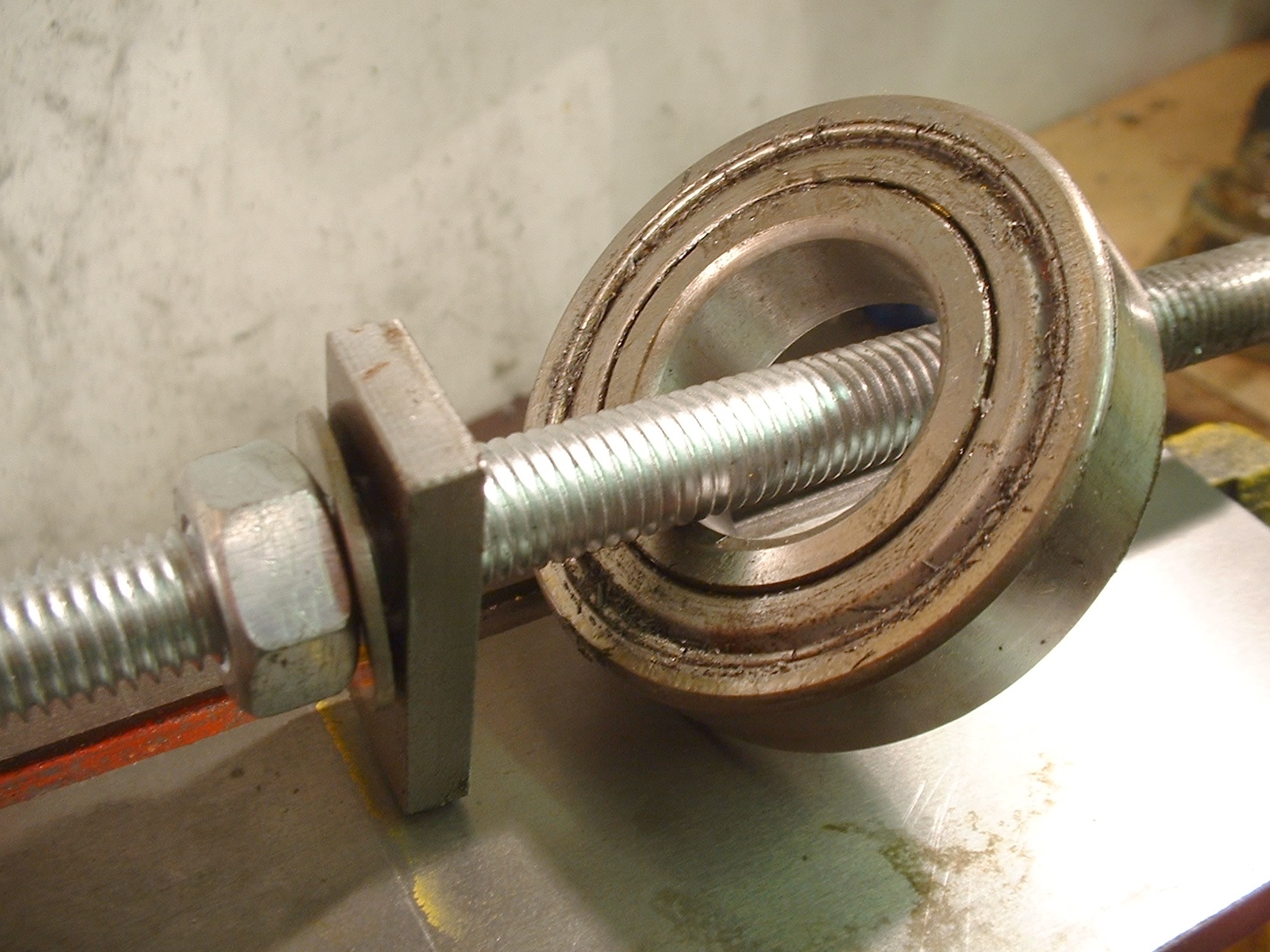
The original rear ball raced bearing removed from a mini lathe.
For a mini lathe where loads are much lighter and the motor is less powerful, another option is to fit angular contact ball bearings. These share the benefits of better control of end loading while being better suited to high-speed use; they also can by exchyanged for standard bearings with no dimensional changes making coinverion rather simpler.. They have become increasingly popular as a choice of mini lathes.
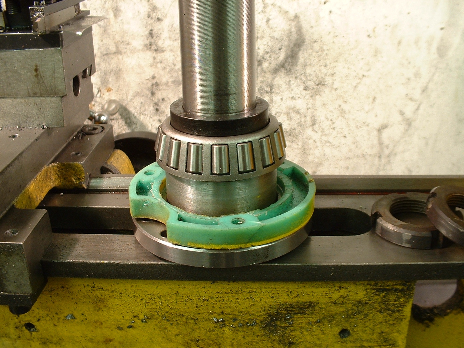
Replacement front inner race with its caged rollers fitted to the mandrel of a mini lathe (together with the front bearing shield and a short spacer).
All of which begs the obvious question – if it ain’t broke, why fix it? I am another traveller on the endless quest for the ‘ideal lathe’. Adding roller bearings would not harm my lathe, and unlike roller bearings, I gain some real control over the bearing adjustment. If they gradually wear, I can take it up properly.
In a second article I will describe my experience in fitting roller bearings to a Mini Lathe, and give my assessment of the effect they have had on the lathe.
See also: Changing the Bearings on a Mini Lathe


