If you find this website useful, please check out my books or visit my Amazon Author page. Or even Buy Me a Coffee!
Workshop
In a Model Engineer's Workshop
I had my first workshop at about the age of fourteen. It was only a draughty, unheated Victorian conservatory, five feet square with a crude bench, but it was my space to make models, electronics and generally star accumulating bits and pieces. It seemed natural enough, after all my father and grandfather both had workshops. Sadly when I went to college at 18, I had to make do with tables and odd corners for about fifteen years, but eventually I got a proper workshop again.
This section of the website will gradually accumulate some of the tools and techniques I've got to grips with over the years. Some of these may have previously appeared in print in a slightly different form.
Making Workshop Tools
The Right Temperature for Hardening Silver Steel
Making a Micro Adjustable Surface Gauge
Accessories and Machines
E. Bourdon's Patent Compound Gauge
Workshop Data
Workshop Ramblings
Are BA Fixings Metric or Imperial?
See all articles tagged WORKSHOP
The tables supplied with the Vertex HV6 are notorious for containing some frustrating errors.
Howard Lewis has prepared a detailed table giving the correct figures,a nd has given me permission to make it available here:
Vertex HV6 Dividing Head corrected table.
The table can be used with any 90:1 ratio dividing head assuming discs with the corrrect numbers of holes are available.
Thanks Howard!
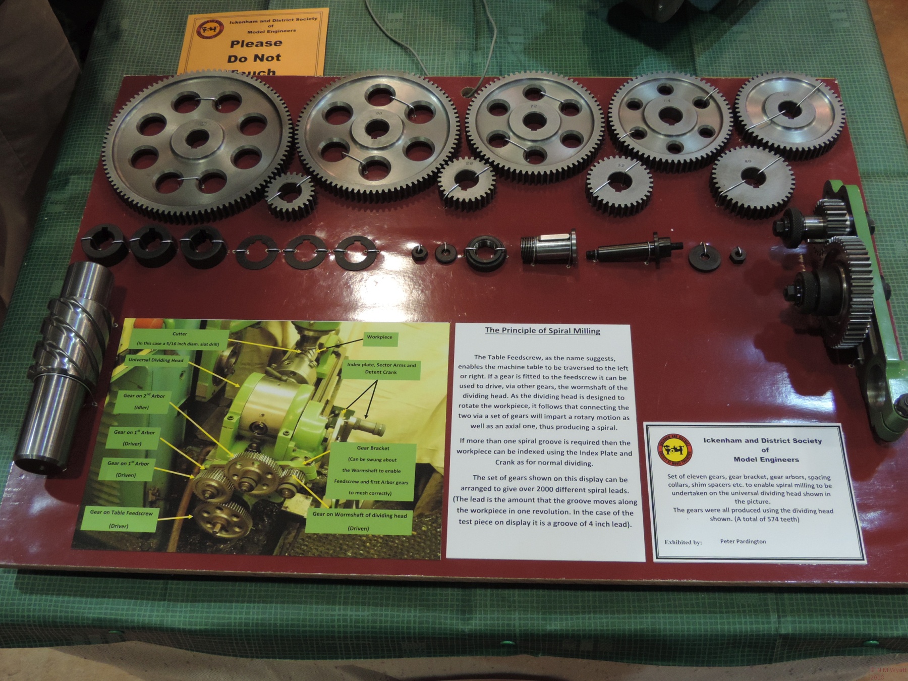
A very fine display of dividing accessories and a technique for making sprials by Peter Pardington of the Ickenham society
- Details
- Category: In a Model Engineer's Workshop
Stub Mandrel is an occasional contributor to the magnificent magazine Model Engineers' Workshop.
The Model Engineers' Workshop Index has been through various permutations. The Official Index is now sustained by David Frith and is available from: www.model-engineer.co.uk/forums/topic/latest-mew-index/
- Details
- Category: In a Model Engineer's Workshop
I'm delighted to let the world know that my first book on a hobby-engineering topic has been published - The Mini Lathe - by Neil M. Wyatt.

The Mini-Lathe by Neil Wyatt
The book covers every aspect of choosing, buying, setting up and using a minilathe. I've had my machine since 1998, so this is a book written by someone who really knows mini-lathes inside out.
With chapters on basic turning, screwcutting, advanced techniques, milling in the lathe, accessories and projects this book is agreat introduction to the hobby of turning and metalworking for owners of any small lathe.
You can buy a copy using this link: THE MINI LATHE
RANKED #9 METALWORKING BOOK ON AMAZON (12 May 2016)
- Details
- Category: In a Model Engineer's Workshop
The X2 mill is a popular entry-level machine for model engineers. It shares many features in common with the popular mini-lathes, and like them it can benefit from a number of relatively inexpensive and straightforward modifications that greatly increase its utility.

An X2 Mill in as received condition
The original design X2-style mills, as sold by many suppliers, share three shortcomings that limit the user’s ability to stretch the machine to its full potential. Firstly, the design of the bracket for the tilting column is poor, leading to a lack of rigidity; secondly the plastic drive gears in the gearbox can fail, especially when making interrupted or heavy cuts. These issues have been addressed by Arc Euro Trade’s new ‘super X2’ which has a brushless DC motor which does not need the two-speed gearbox as well as, unique to Arc, a more rigid, non-tilting column. This new version also has a larger table derived from the X1 mill. The third issue is that, as standard, the X2 mills are fitted with the same deep groove ball bearings as mini lathes. Because these bearings are not designed to take preload or heavy axial (along the spindle) loads, this arrangement is not ideal for either a lathe or a mill, potentially affecting surface finish. A roller bearing conversion for mini-lathes is a popular upgrade. Unfortunately roller bearings are not an ideal solution for the X2, due to their greater thickness which means they are not really suitable for the existing lathe spindle.
The good news for owners of the old-style X2 mills is that there are now tried and tested solutions to all three of these issues, which can allow owners of the ‘old style’ X2 mill to achieve its potential. This page looks in detail at the first, and most significant shortcoming - rigidity.
Rigidity
The column of an X2 mill is mounted onto the base via a right-angle bracket. It is clamped to this by a very large nut and bolt, tensioned against a belleville washer. This arrangement allows the column to tilt left and right, and after any disassembly the vertical adjustment of the column needs to be checked, as described later.
The sheer size of these fixings appears to prevent any problems - the column is solidly attached to the bracket. It is the less obvious joint between the bottom of the bracket and the base of the mill where issues arise. The fixing bolts for the bracket are all along one edge, virtually in a straight line.

The three fixings in a straight line
This means there is poor resistance to flexing at the joint. This situation was not helped by (on my machine) a poorly machined finish to the mating surfaces, which also manifested itself in a slight fore-aft error in the alignment of the column. Because of the geometry of the mill, just tiny movement at this joint can be magnified into discernible movement at the tool tip.
Testing Alignment of the Column
Start by switching off and cleaning up the mill before you start. The fore and aft (and sideways) alignment of the column can be tested by fixing a dial indicator off a bar held in the spindle –by a chuck or collet, the accuracy doesn’t matter in this case. Place a piece of clean, flat glass on the mill table beneath the spindle and adjust the indicator so its tip rests on the glass. Set it up so that when you rotate the spindle the indicator traces a circle 6-9 inches in diameter on the glass. Movement of the needle will rapidly demonstrate any errors in side to side or up and down alignment of the spindle. Deflection when the head is gently pushed will highlight any lack of rigidity. Expect greater deflection under back and forth pressure than side to side – this is the problem we will now tackle.

Tramming the Mill column
This process is one you should carry out every time you move the column off the vertical and then back again. You should also do it as a check from time to time, especially after heavy or interrupted cutting or if the finish you get shows the uneven signs of an out-of square cutter.
Improving the Fit of the Mounting Bracket
The first step to increasing rigidity is to scrape the bottom of the mounting bracket to a better fit on the base. If you column has perfect fore and aft alignment and no obvious flex under light loads, then you may not wish to do this, so jump straight to the section on making a stiffener plate. If you wish to scrape in the bracket start by removing the concertina shield between the table and the column. You can now see the three screws that fix the bracket in place, but leave them alone for now. Proceed by removing the mill head from the column. This is done by first unscrewing the white nylon bumper at the top of the column and loosening off the gib strips. Now you can support the head and carefully disconnect the spring counterbalance and wind the head right up and lift it free. You can then loosen off the big nut at the back of the column, remove the dished belleville washer and lift the column free. It is quicker to work keeping the head attached to the column, but I don’t advise this, as the combination is very heavy, unless you have someone to help with lifting it in and out of position. Whichever way you work, do not leave the column unsupported whenever the securing nut is not fully tightened.
This is a good moment to ensure that the rack attached to the column is firmly screwed in place. It is not unusual for the two M6 countersunk screws to become loose.

Rack on the Column
With the column carefully set aside, you can now unbolt the bracket. The starting point for addressing the rigidity problem is by carefully scraping the joint between bracket and base to a much better fit. Unfortunately, I didn’t record this process with pictures. Using engineer’s blue; this is not the same as marking out blue, it is a fine intense paste that doesn’t dry - I use ‘Stuart’s Micrometer Paste’, traditionally one tin lasts a lifetime. Apply a very thin layer to the bottom of the bracket, then put the bracket in pace on the base and move it around in small circles. The blue will transfer to the areas where the two surfaces are in contact. For my mill, it was clear contact was limited to only about a quarter of the joint, mostly near the screw holes. This made it relatively easy for the column to tilt.
If you carefully scrape away metal from these areas, and keep repeating the process, eventually you will end up with both surfaces having excellent contact across a much larger area. Traditionally scraping is done with specialist tools and leaves a highly decorative pattern on the metal. In this situation, I just wanted to increase the area of contact and was not worried about making a pretty pattern. I used a broad-ended HSS parting tool, temporarily mounted in a wooden handle. To my surprise I found that the tool needed regular honing to keep it sharp and cutting freely.
This is the tedious bit – you MUST keep assembling the mill and checking the fore and aft alignment of the column at regular intervals. Again, do this with a dial gauge mounted from a bar held the mill, so that it can be rotated by hand in a circle over a sheet of flat glass placed on the milling table. The gold standard is when the needle of the gauge shows no movement during an entire circle. What you are aiming to do is minimise errors across a cut, so bear in mind that even a couple of thousandths across an eight inch circle may be undetectable at the diameter of a typical milling cutter.
It is obviously possible to remove too much material from the front or back of the contact patch, so take care. In my case, I already knew my column was tilted backwards slightly, and I was able to bias the removal of metal so that as well as increasing the size of the contact patch, I corrected this small, but irritating, error of alignment. It is always easier to work with a bias one way or another, than just improve the fit of two surfaces that are already aligned.
Because of the need to reassemble and break down the mill for the checks, this procedure took several hours work, taking it very gently. Both the air and my hands were thoroughly blue by the end of the process, but I got the contact patch up to about 75-80% and much better distributed. The difference in rigidity of the mill was surprisingly noticeable.
Fitting a Stiffening Bracket
The final step to completely stiffen up the mill is much simpler, and some as some users have found it solves all their problems without the effort of scraping in the bracket. If your mill already has good fore and aft alignment, you may wish to just take this step. The solution is just a simple stiffening plate at the back of the column. There are examples a good 1/2 thick, while others have had success with steel plate down to 3mm thick. I made mine from 5mm steel from an old loudspeaker stand, and I would suggest that this is probably as thin as you should go.

The stiffening plate fitted to the back of the X2 Mill
The plate is roughly triangular (the shape is not important) and with three holes. The largest hole is for the bolt which takes the belleville washer and nut at the back of the column. The two 10mm holes are for high tensile bolts into the back of the base of the mill. The dimensions are not critical, and you should make the plate to fit your mill, but here are the measurements for mine:

Dimensions for an X2 Mill Stiffening Plate
I suggest checking under the base of your mill to check the best place to drill and tap the M10 holes, as machines may differ. Look for a place where there is plenty of ‘meat’ in the casting. If you make the holes in the plate tapping size for M10 first, you can then hold it in pace with the big nut and spot through to mark the base casting. You will probably need to use a portable drill for these holes as the mill base is unlikely To fit on the table of most drilling machines. I found the cast iron base drilled and tapped freely, even at these large sizes. As you won’t be able to use a tapping guide on the angle surface, it is very important to start with the taper tap. Although it is tempting to skip its use on softer materials, for larger holes the long, slow lead on a taper tap guides its somewhat making it easier to tap a square hole.
Before fitting the two M10 screws, you need to make some shaped spacers to fit between the plate and the base of the mill. Because castings vary, you will have to shape these by hand. File them so you can push them into place with their central hole lined up with those in the base and the plate. If you drill the centre hole oversize, this will compensate for any small misalignment.
Spacer fitted between the plate and the base of the mill
Open up the holes in the plate to 10mm, and refit it tightening up the two M10 screws first, before finally tightening up the big nut at the base of the column. Note that this brace is not taking any great load, its job is just to remove any tendency for the back of the column to move up or down.
Scraping had brought my mill into good alignment and helped with rigidity, but the fitting of a brace at the back of the mill made a huge improvement. Now the mill was more rigid I could take better advantage of the machine’s capability and take bigger cuts. I proceeded to mill some reasonably tough steel using a 11.5mm slot drill. The chips flew far and wide, but Murphy’s law decreed that the extra load this put on the gears resulted in their disintegration into a little pile of small white chunks.
This page is based in part6 on my article for Model Engineers' Workshop magazine.
- Details
- Category: In a Model Engineer's Workshop
Making a Set of Quick Change Toolholders
This article follows on from the first part on making the QCTP block.
You can download a free set of plans for the QCTP design with this link.
The basic toolholder is a 2” length of 1” square mild steel. Each one needs a dovetail cutting in the back. I made a template from aluminium sheet that was a good fit on the toolpost block dovetails, marked with two lines 2” apart, it provides a quick check that the dovetails are properly placed and proportioned.

The dovetail template
If you can get a good long length of steel, I suggest you ‘mass produce’ a quantity of blanks (I cut 9 from about 20” of bar), carrying out one operation at a time. Start off by milling a 1/4” deep slot in the middle of each blank 0.710” wide. This is the width across the narrow base of the dovetails. Use a good-sized slot drill (I used 11.5mm), to ensure you get a consistent width. Aim to get the slot in the centre of the blank, though a rule dimension or measuring from the template is fine. The depth should be at least 0.250” and reasonably accurate (too deep means the lever needs to turn to far, which may be inconvenient, but keep the same depth for each toolholder, so the handle always locks in the same place). Similarly, the width should be as accurate as possible in order to facilitate accurately cutting the dovetail itself.
My procedure was as follows: Cut one side of the slot in two passes to exactly 0.250” deep. Now take further cuts at the full 1/4” depth until the slot is full width. A digital readout will facilitate this, just subtract the cutter width from the slot width, and zero the readout when cutting the first side. Once you have one blank slotted, ditto repeato (to coin a phrase) until you have a pile of prepared blanks.

A toolholder blank, with a plain slot
Now exchange your slot drill for a dovetail cutter. For each blank start by adjusting the cutter to 0.250” depth. Take suitable passes along one side of the slot until the witness of the vertical edge of the slot disappears. Zero the digital readout (or your handwheel index). Now repeat on the opposite edge of the slot – you should find that just removing the witness on the second edge creates a dovetailed slot that is just a bit too tight. Gradually widen the slot until the dovetail is an easy fit on the toolpost block, ensuring that the dovetails are clear of swarf before testing the fit. Make this test without removing the toolholder blank from the mill so you don’t loose the index setting. Once you have a suitable fit, note the DRO or index reading.

A finished toolholder blank with its dovetail
You can now machine the dovetails on the remaining blanks, working to the same reading in confidence that they should all be a good fit on the toolholder (photo 10). In practice, I tested the fit ten thou before reaching the ‘ideal width’ to be on the safe side. With a suitable fine file, tidy up the edges of all the blanks and make sure they are all a good fit on the toolpost.
Height Setting Studs and Buttons
These studs and their nuts or buttons (figure 8) are what give the quick release toolpost its repeatability. Drill and tap the blind M5 holes for the studs in the blanks. Note how close they are to the dovetails – this ensures a good overlap of the buttons and the toolpost and minimises interference between the buttons and tool fixing screws. The studs themselves are just lengths of M5 studding.

How the height setting buttons work
The height setting buttons can be finished to suit you own preferences, all that matters is that they have a suitable flat base that will overlap the toolpost. To make the height setting nuts I knurled a diamond knurl along just over half of a length of 1/2” brass bar. I then reversed it and held it in the chuck, using some aluminium shim to prevent damage to the first section, and then knurled the remainder of the bar. I used a 1/8” parting tool to create the decorative effects, repeated along the bar, and then a 1/16” parting tool to cut of the individual nuts.
Again using the aluminium shim for protection, I faced off the pip left by parting and then drilled and tapped each nut M5. I used ordinary M5 nuts to lock these height setting nuts, you may wish to make a batch of smaller brass lock nuts.
Customising the Toolholders
It’s now up to you to decide what different types of toolholder you need and how many of each type. Take your time, and enjoy the variety of tasks after all that repetition work!
Standard Toolholders
The standard size HSS tool for a C3 lathe is from 5/16” HSS. The standard toolholder for these bits requires a suitable slot to be milled along the length of the holder (as in the drawings) and threaded holes being made for four holding screws. If you can get M5 grub screws these are a neat solution, but if not Screwfix (usual disclaimer) supply 16mm stainless steel cap screws at a very reasonable price for 50. The ones I obtained have the advantage of ends turned neatly and in such a way that they won’t burr over.

A standard QCTP toolholder
These holders can also be used for 1/4” HSS, but if you prefer this size you may find you can economise and make toolholders from 3/4” bar instead. If so, you will need to use grub screws to make sure they don’t foul the height setting nuts.
The ends of the toolholders can be treated in whatever way you wish. I plan to bevel mine at about 30° for appearance sake – it will not materially affect their strength.
Boring Bar
For boring bar holders, you need to drill and, ideally, ream a hole that is a good fit for your boring bar along the length of the holder. I prefer two or three screws bearing on the bar to hold it in position. Others may prefer to slot the holder and make a clamp arrangement. Ideally, the hole for the boring bar should be reamed to size. I drilled undersize and used a hand reamer to finish the hole.

QCTP Boring Bar Holder
Be careful not to overtighten the clamp screws, especially if your boring bar is unhardened steel, as you could damage the surface of the boring bar, making it hard to remove. If this is a concern, use a clamp arrangement instead, or put brass or copper pads down the screw holes. I have a long inserted cutter bar and several smaller HSS boring bars with 3/8” diameter. The former is hardened steel and the latter are HSS, so I am not worried about this issue.
I made two of these holders – the first has a 0.375” hole that fits both my larger boring bar and the other is bored 0.25”. For the smaller one I have also made a sleeve for a very small 3/16” bar.
Parting Tool
There are several different styles of parting blade available, some are rectangular in section, others have some relief on the sides. I made my holder (figure 10, 11)to suit 1/16” by 5/16” section HSS from Arc Euro Trade (usual disclaimer). This shape allows the use of a flat-sided holding groove, but you will still need to obtain or make a small dovetail cutter to form the bottom edge of the groove. Such a cutter can be made from 3/8” silver steel by turning a short cone on the end, filling a few teeth and hardening and tempering it. Such a simple tool will be fine for this task, if a bit crude for making proper dovetails.
Non-rectangular blades will require a holding groove to match their shape. This could be considerably more challenging to make, but the same basic clamping mechanism could be used.
The clamping block only extends for half the length of the groove for two reasons – it concentrates the clamping force where it is needed, and it gives it a more positive location. I suggest fitting the block in place before drilling tapping size for the clamp screw right through both components.
DTI Holder
As a DTI is not under heavy loads (hopefully!) it can be made from steel or a length of 1/2” thick aluminium alloy. The drawing is almost redundant – this is an over-length toolholder with a 3/8” (or whatever suits your DTI) hole and a clamp screw. This is another opportunity to have a bit of fun, and see if you can make a nice shape, rather than just something blandly functional – one suggestion I would make is to make the clamp screw from brass with a knurled knob, to make sure it doesn’t get overtightened. A right handed version is drawn, suitable for holding a DTI to check the concentricity of work held in a 4-jaw chuck. A left-handed version could be modified to support a ‘Verdict’ type lever indicator for checking the truth inside a bore.
Knurling Tool
One of the very first workshop tools I made was an unsophisticated, but effective, clamp knurling tool. This was made with a bar that clamped in the four-way toolpost. I simply cut a dovetail in the bar and added a height setting stud. Although this hasn’t made the tool any prettier, it works well (I knurled along length of 1/2” diameter brass with this device to make the height setting buttons) and demonstrates the principle that any tool that can be fixed in the toolpost can potentially be modified in this way.

Simple scissors knurl modified to fit the QCTP
A Few More Thoughts…
Another idea is a holder reamed for an MT1 taper, a second is to make my keyway slotting tool fit the toolpost. Yet another is to modify my toolpost drill. Equally a toolpost grinder, multi-tool or any other device could be modified to fit on the dovetails. I’m sure there are many other possibilities.
Anyone who follows the discussions on the ME web forum will know how popular tangential toolholders are. I have made one of these for 1/4” HSS and it has proven very useful. I have made a QR toolholder version, and have included a concept drawing. This is something I have not seen elsewhere, but it seems blindingly obvious (perhaps I should have patented it even so). Note that as the toolbit can be adjusted separately for height, the holder needs to be set as low as possible, and maximise the amount of metal supporting the toolbit. This is why the lower part of the dovetailed body will need to be cut away.
As it is now so easy to adjust the height of your tools to be spot on with this new toolpost, the value of a height setting gauge becomes apparent! It also means there is no excuse not to swap tools as often as you need, rather than making do with the same tool for turning and facing, or accepting the finish from roughing tool. Hopefully, this means the standard of my turning will improve!
This article follows on from the first part on making the QCTP block.
You can download a free set of plans for the QCTP design with this link.
- Details
- Category: In a Model Engineer's Workshop
Subcategories
Reference Information Article Count: 5
This is a repository for all sorts of workshop data and background information.
Page 1 of 3
- You are here:
-
Home

- Workshop