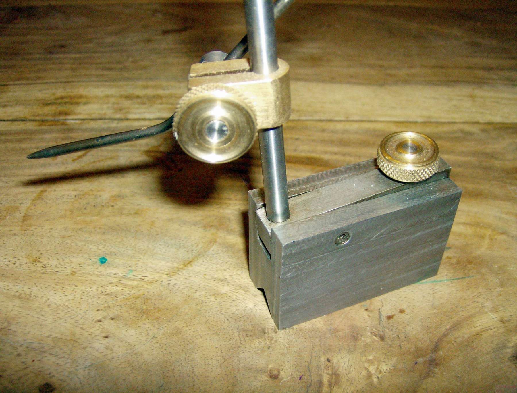
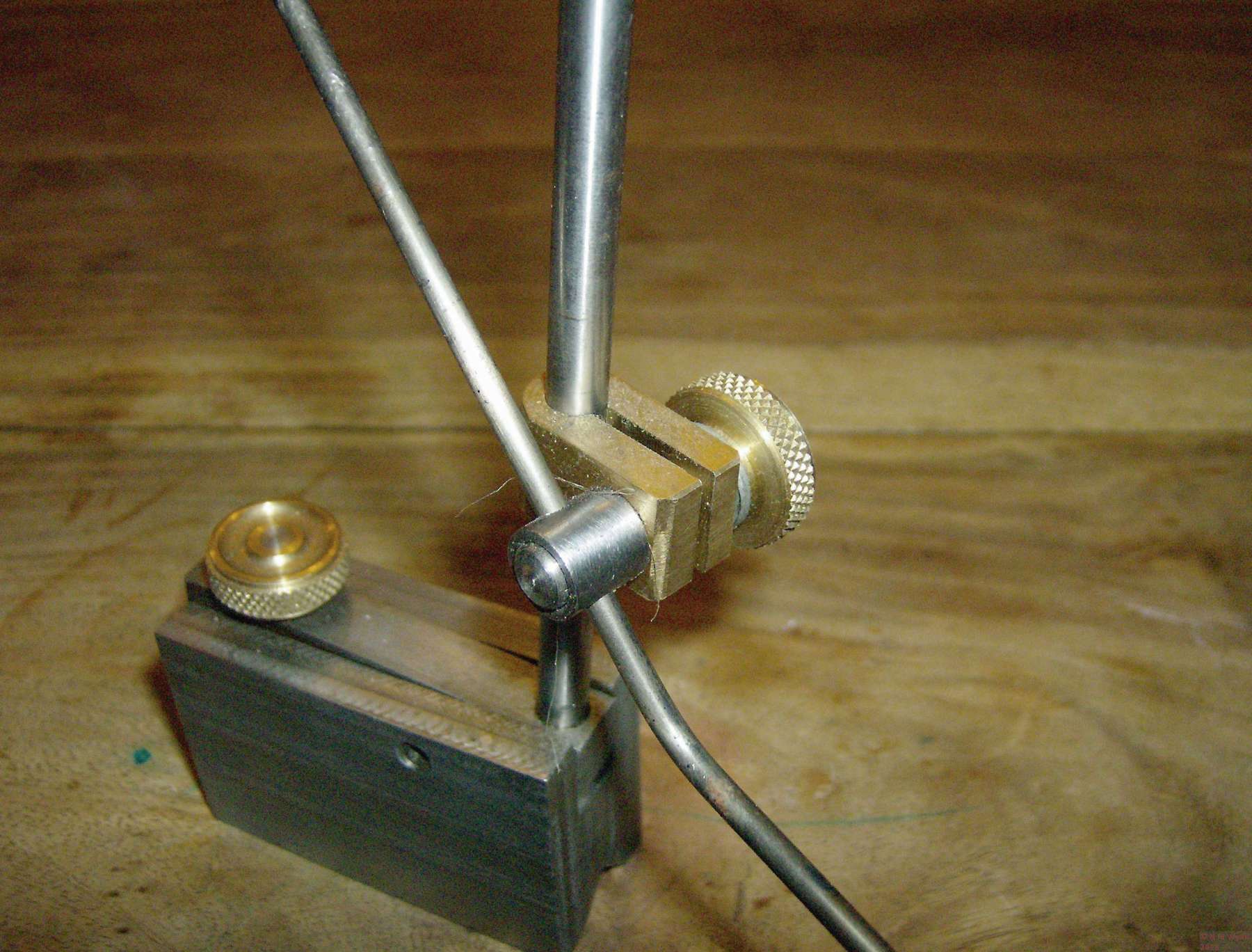
Micro-Adjustable Surface Gauge
A surface gauge is an essential aid to accurate marking out. What is needed is a stable, flat bottomed base with a pillar and clamp to hold a scriber, allowing lines to be made truly parallel with the top of a surface plate. Such a device has many other uses, such as helping set work in a four-jaw chuck or any other task where the ability to ‘mark’ a point in space with the end of a scriber is needed.
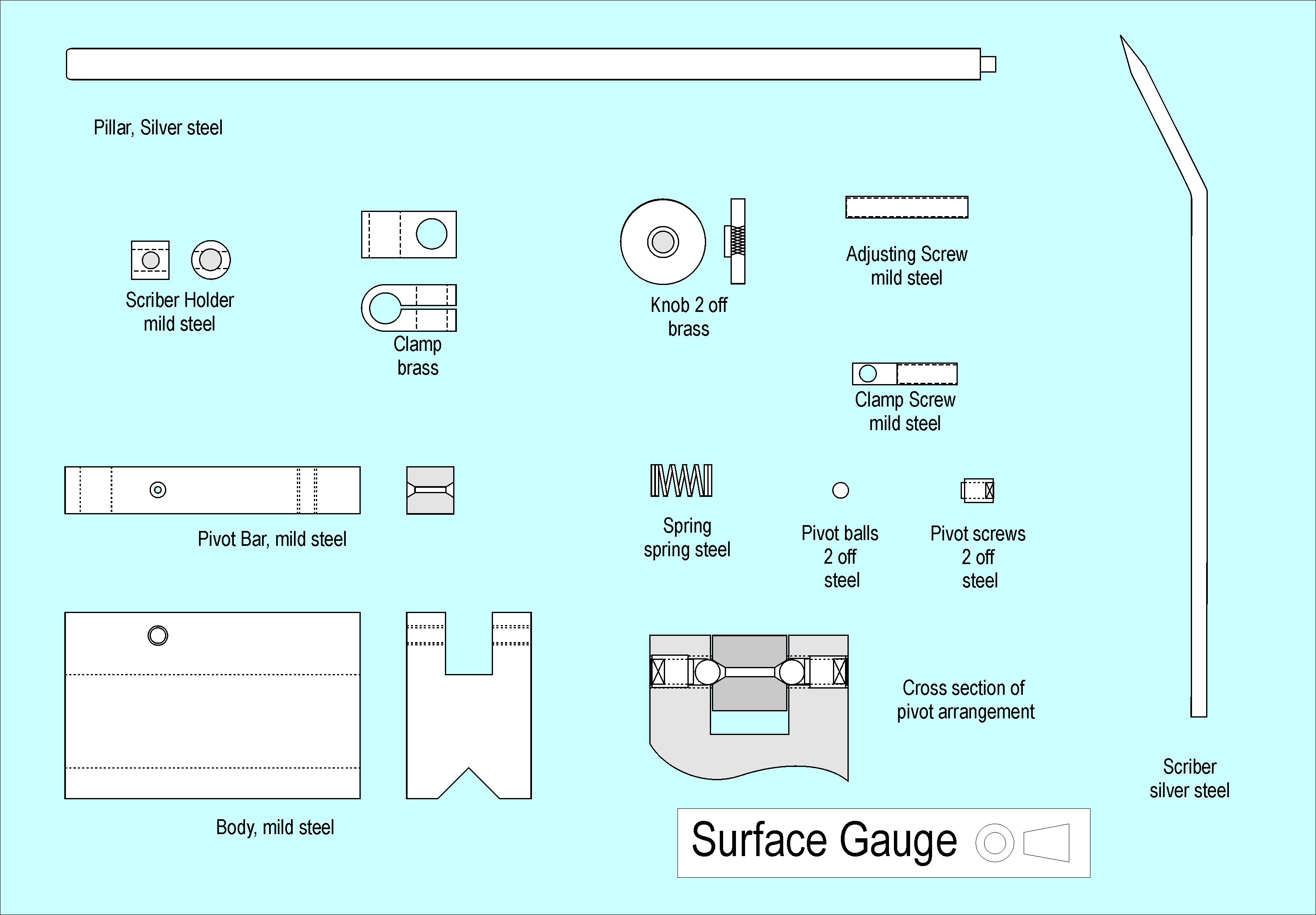
A basic ‘scriber on a post’ works well, but sometimes a more robust device is needed, or perhaps the ability to make a fine adjustment to the height of the scriber is useful. A design that has been made (with many detail variations) by hundreds of apprentices over the years is the answer, and it relies on the fact that the pillar does not need to be vertical. As long as the base of the body is flat, and there is no play anywhere, the whole thing is inherently accurate (at least in Euclidean space – and if your workshop is on the edge of a black hole you may have other worries!) The design in the drawings uses a tilting bar in a heavy base. No dimensions are given, make the parts to suit what offcuts you have.
Plan for the Surface Gauge
The pillar is mounted in a tilting bar held between two ball bearings. Silver steel of 1/4” (or 6mm) diameter is fine for the pillar, do not harden it, as this may cause distortion. Ground mild steel would do just as well for the pillar. I tidied up a piece of steel bar by skimming the ends in the mill and draw filing. The hole for the pillar is best made in the lathe, as is the cross hole for the pivot, but the threaded hole for the adjuster is not critical. Thread both hole and pillar to match: 1/4” BSW, 0BA or M6 will do fine. Carefully open out the upper part of the hole, so that some of the full diameter of the pillar enters the hole, holding it in line. You can also use a force fit, a retaining adhesive or even a set screw to fix the pillar in place.
Both ends of the pivot hole need to be countersunk, using a centre drill of the same diameter as the ball bearings for the pivots, make a countersunk hole to the full diameter of the drill, but don’t drill past the tapered section of the drill. Follow up with a drill the same size as the tip of the centre drill. Now turn over the bar and carefully align the hole with the drill before clamping the bar in place. Now swap back to the centre drill and create another countersink.
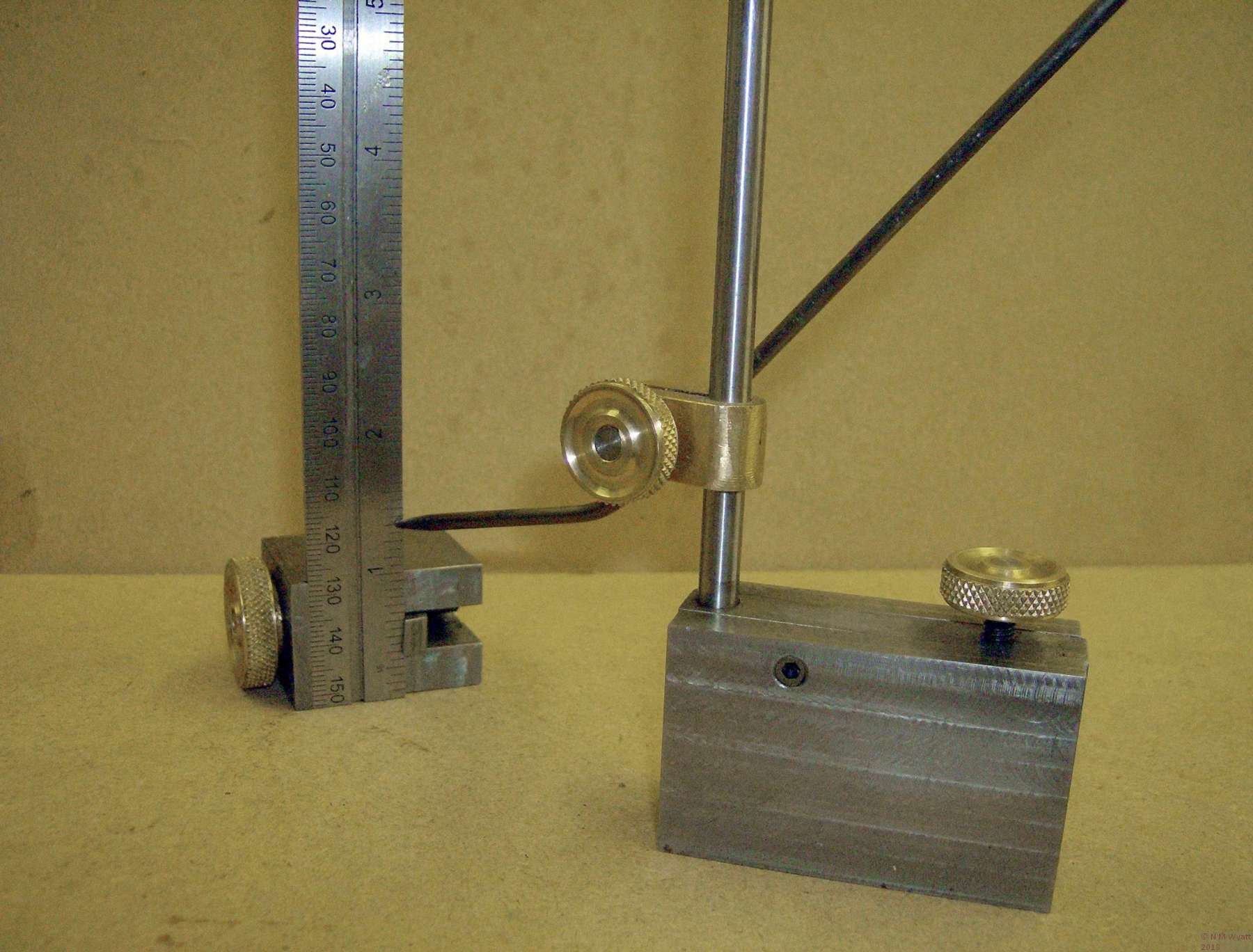
Setting the height of the gauge against a rule
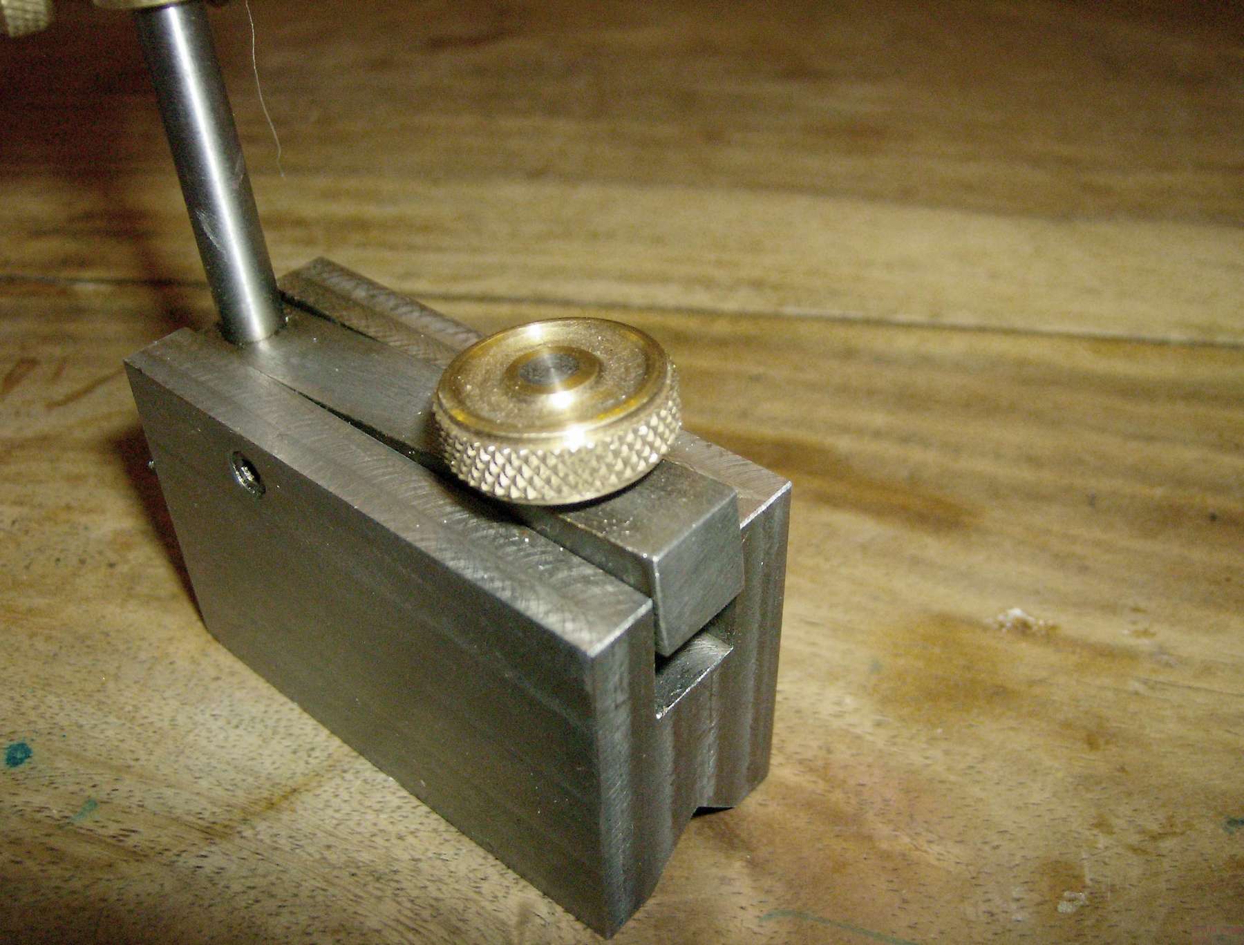
The base is a section of mild steel bar, skimmed on all sides (on lathe or mill) to get it square. The V-groove in the base can be milled with a suitable cutter, holding the base in a pair of v-blocks as in the photograph. This allows the base to sit on a curved surface (or the inverted-v bed of my lathe), but if all you want is to ensure the block sits fairly on a flat surface, then a simple recess is sufficient.
The groove on top of the base should be milled out to be a sliding fit for the tilting bar, but drill the cross-hole for the pivots first, as it is essential that these are in line. These pivot holes need to be a close fit of the ball bearing pivots. For the record, I used two 1/8” ball bearings and tapped the holes M5 for some flat-tipped grub-screws. It should now be possible to mount the tilting bar between two ball bearings held in the tapped holes using a pair of setscrews. The bar should move freely, even when the bearings are held quite firmly.
Locate the correct position for a stepped hole to take the return spring under the pillar. The return spring should be reasonably strong, but it does not need to be excessively stiff – in use the action of scribing pushes back against the adjusting screw and assists the spring. Make a suitably decorative pair of knurled nuts, one for the clamp, and one to secure to the end of the adjusting screw for the tilting bar. Take a little time to set the bearings just right, and you will be rewarded with a silky-smooth action to equal any bought piece of equipment.
There's knothing kwite like a krisply knurled knut :-)
The simplest and best clamp for such a device is shown in the drawings. A central shaft is threaded at one end and has a hole for the scriber at the other. This is threaded through the body of the clamp, a sleeve fitted around the scriber end and the scriber inserted through both sleeve and shaft. Provided the clamp body is good fit on the pillar, then a simple knurled nut on the thread will pull the parts together with ample force to secure everything in place. Brass is a good material for the clamp body (which is best finished by draw filing), while the other parts of the clamp can be mild steel.
Details of the Clamp
The scriber should be made from silver steel (3/32” or 2.5mm is good size), cut it to length and carefully turn a taper on each end, finishing with a tiny 60° point. If you use files to do this, take great care, making sure they have secure handles and that you wear safety goggles – if the file contacts the chuck jaws it can be thrown into your face. Bend the scriber about 30° near one end – this will help when setting it low down. Hardening such a long, thin piece can be difficult. It may be easier to heat it to a bright red along its length using a gas cooker or a camping stove, rather than a blowtorch, picking it up at the centre with a pair of pliers and plunging it rapidly into a bowl of water. An alternative is to heat and quench each end separately, but this will leave the centre of the scriber very soft, and it may bend in use.
Similarly there are two approaches to annealing the scriber. Heating the centre until the ends turn a dark straw colour will leave the ends hard and the centre less so, but again my fear is that the centre will be easily bent. I cook my scribers at gas mark 5-6 which gives a good colour and even temper along the whole length. Remember though, gas ovens are not precision instruments! I know my oven runs hot, so I suggest you put the work in at a low number, and then ‘tweak’ it up every ten or fifteen minutes, until you get the right ‘bronzy’ dark straw colour.

