Making a Set of Quick Change Toolholders
This article follows on from the first part on making the QCTP block.
You can download a free set of plans for the QCTP design with this link.
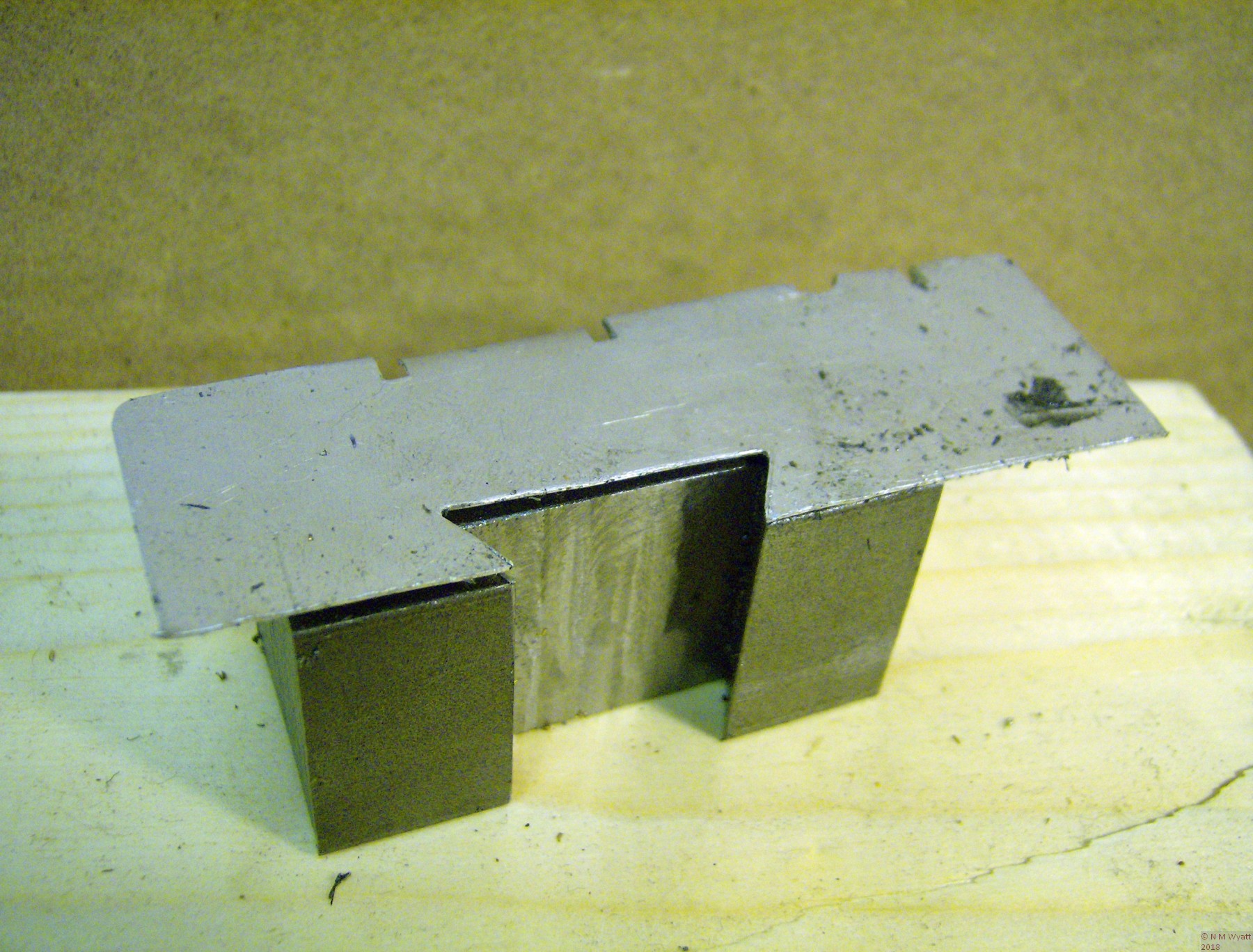
The basic toolholder is a 2” length of 1” square mild steel. Each one needs a dovetail cutting in the back. I made a template from aluminium sheet that was a good fit on the toolpost block dovetails, marked with two lines 2” apart, it provides a quick check that the dovetails are properly placed and proportioned.
The dovetail template
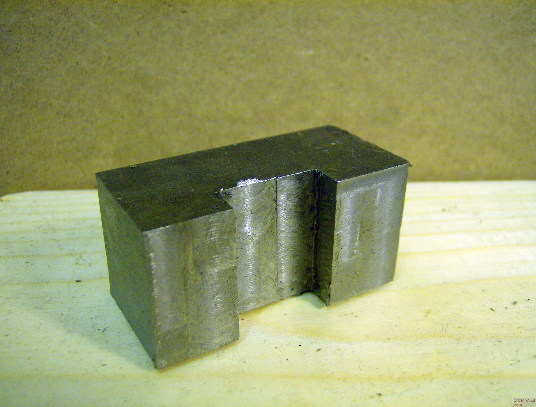
If you can get a good long length of steel, I suggest you ‘mass produce’ a quantity of blanks (I cut 9 from about 20” of bar), carrying out one operation at a time. Start off by milling a 1/4” deep slot in the middle of each blank 0.710” wide. This is the width across the narrow base of the dovetails. Use a good-sized slot drill (I used 11.5mm), to ensure you get a consistent width. Aim to get the slot in the centre of the blank, though a rule dimension or measuring from the template is fine. The depth should be at least 0.250” and reasonably accurate (too deep means the lever needs to turn to far, which may be inconvenient, but keep the same depth for each toolholder, so the handle always locks in the same place). Similarly, the width should be as accurate as possible in order to facilitate accurately cutting the dovetail itself.
My procedure was as follows: Cut one side of the slot in two passes to exactly 0.250” deep. Now take further cuts at the full 1/4” depth until the slot is full width. A digital readout will facilitate this, just subtract the cutter width from the slot width, and zero the readout when cutting the first side. Once you have one blank slotted, ditto repeato (to coin a phrase) until you have a pile of prepared blanks.
A toolholder blank, with a plain slot
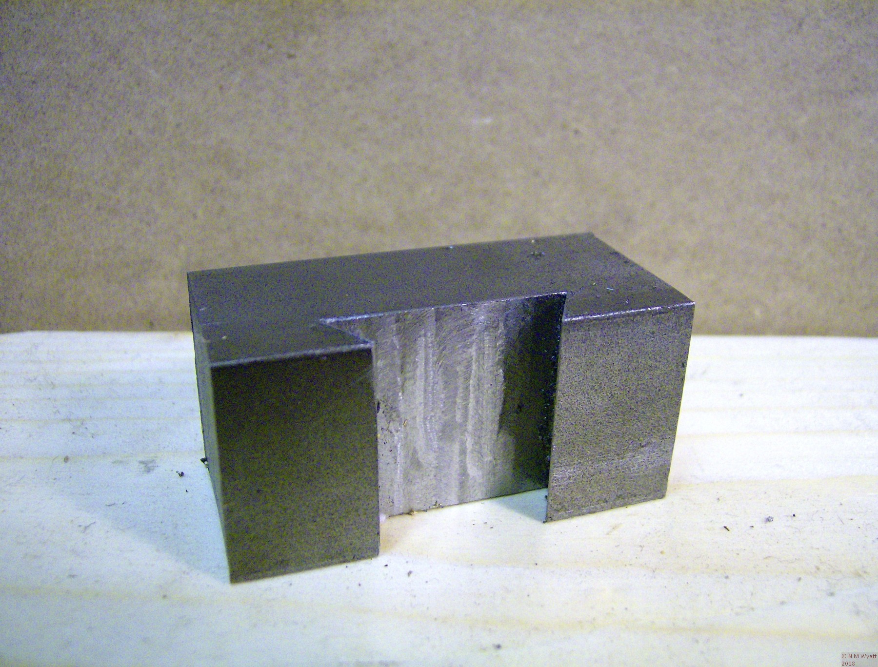
Now exchange your slot drill for a dovetail cutter. For each blank start by adjusting the cutter to 0.250” depth. Take suitable passes along one side of the slot until the witness of the vertical edge of the slot disappears. Zero the digital readout (or your handwheel index). Now repeat on the opposite edge of the slot – you should find that just removing the witness on the second edge creates a dovetailed slot that is just a bit too tight. Gradually widen the slot until the dovetail is an easy fit on the toolpost block, ensuring that the dovetails are clear of swarf before testing the fit. Make this test without removing the toolholder blank from the mill so you don’t loose the index setting. Once you have a suitable fit, note the DRO or index reading.
A finished toolholder blank with its dovetail
You can now machine the dovetails on the remaining blanks, working to the same reading in confidence that they should all be a good fit on the toolholder (photo 10). In practice, I tested the fit ten thou before reaching the ‘ideal width’ to be on the safe side. With a suitable fine file, tidy up the edges of all the blanks and make sure they are all a good fit on the toolpost.
Height Setting Studs and Buttons
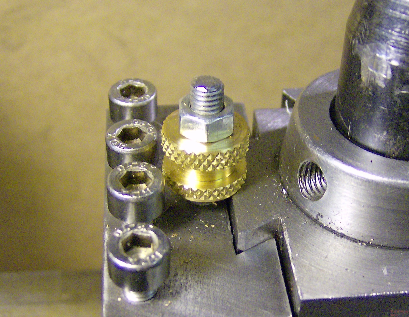
These studs and their nuts or buttons (figure 8) are what give the quick release toolpost its repeatability. Drill and tap the blind M5 holes for the studs in the blanks. Note how close they are to the dovetails – this ensures a good overlap of the buttons and the toolpost and minimises interference between the buttons and tool fixing screws. The studs themselves are just lengths of M5 studding.
How the height setting buttons work
The height setting buttons can be finished to suit you own preferences, all that matters is that they have a suitable flat base that will overlap the toolpost. To make the height setting nuts I knurled a diamond knurl along just over half of a length of 1/2” brass bar. I then reversed it and held it in the chuck, using some aluminium shim to prevent damage to the first section, and then knurled the remainder of the bar. I used a 1/8” parting tool to create the decorative effects, repeated along the bar, and then a 1/16” parting tool to cut of the individual nuts.
Again using the aluminium shim for protection, I faced off the pip left by parting and then drilled and tapped each nut M5. I used ordinary M5 nuts to lock these height setting nuts, you may wish to make a batch of smaller brass lock nuts.
Customising the Toolholders
It’s now up to you to decide what different types of toolholder you need and how many of each type. Take your time, and enjoy the variety of tasks after all that repetition work!
Standard Toolholders
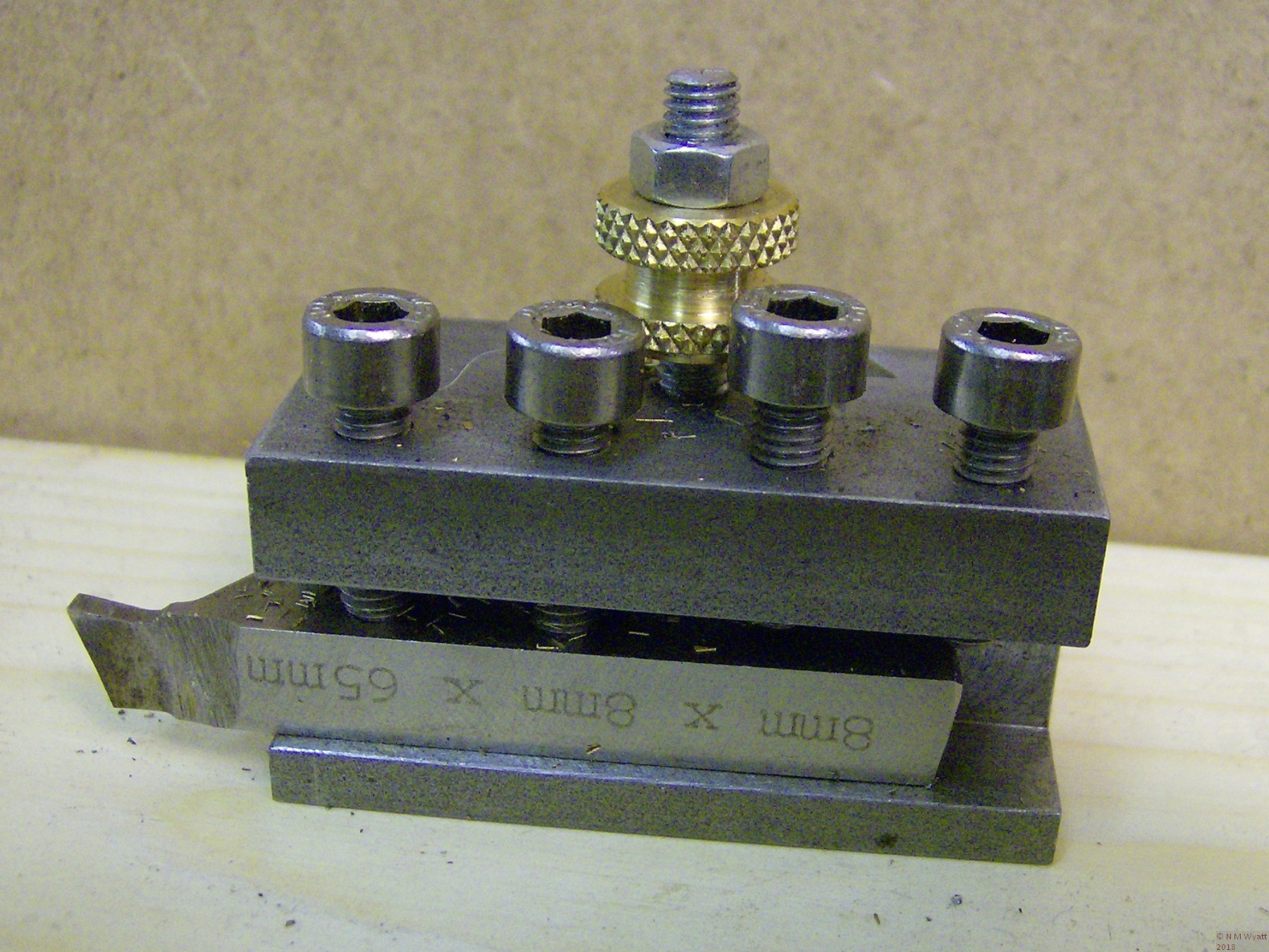
The standard size HSS tool for a C3 lathe is from 5/16” HSS. The standard toolholder for these bits requires a suitable slot to be milled along the length of the holder (as in the drawings) and threaded holes being made for four holding screws. If you can get M5 grub screws these are a neat solution, but if not Screwfix (usual disclaimer) supply 16mm stainless steel cap screws at a very reasonable price for 50. The ones I obtained have the advantage of ends turned neatly and in such a way that they won’t burr over.
A standard QCTP toolholder
These holders can also be used for 1/4” HSS, but if you prefer this size you may find you can economise and make toolholders from 3/4” bar instead. If so, you will need to use grub screws to make sure they don’t foul the height setting nuts.
The ends of the toolholders can be treated in whatever way you wish. I plan to bevel mine at about 30° for appearance sake – it will not materially affect their strength.
Boring Bar
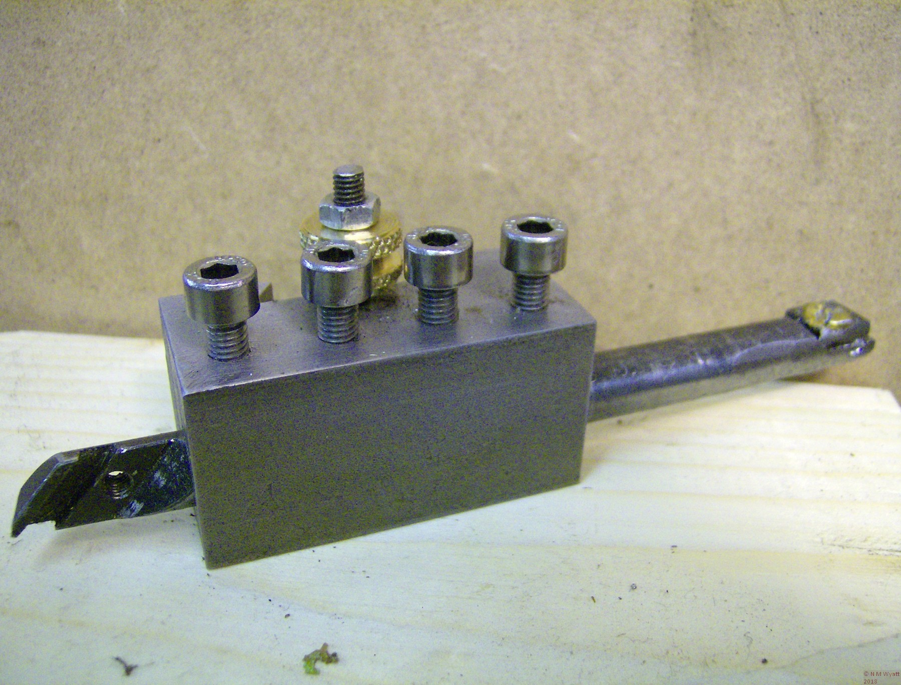
For boring bar holders, you need to drill and, ideally, ream a hole that is a good fit for your boring bar along the length of the holder. I prefer two or three screws bearing on the bar to hold it in position. Others may prefer to slot the holder and make a clamp arrangement. Ideally, the hole for the boring bar should be reamed to size. I drilled undersize and used a hand reamer to finish the hole.
QCTP Boring Bar Holder
Be careful not to overtighten the clamp screws, especially if your boring bar is unhardened steel, as you could damage the surface of the boring bar, making it hard to remove. If this is a concern, use a clamp arrangement instead, or put brass or copper pads down the screw holes. I have a long inserted cutter bar and several smaller HSS boring bars with 3/8” diameter. The former is hardened steel and the latter are HSS, so I am not worried about this issue.
I made two of these holders – the first has a 0.375” hole that fits both my larger boring bar and the other is bored 0.25”. For the smaller one I have also made a sleeve for a very small 3/16” bar.
Parting Tool
There are several different styles of parting blade available, some are rectangular in section, others have some relief on the sides. I made my holder (figure 10, 11)to suit 1/16” by 5/16” section HSS from Arc Euro Trade (usual disclaimer). This shape allows the use of a flat-sided holding groove, but you will still need to obtain or make a small dovetail cutter to form the bottom edge of the groove. Such a cutter can be made from 3/8” silver steel by turning a short cone on the end, filling a few teeth and hardening and tempering it. Such a simple tool will be fine for this task, if a bit crude for making proper dovetails.
Non-rectangular blades will require a holding groove to match their shape. This could be considerably more challenging to make, but the same basic clamping mechanism could be used.
The clamping block only extends for half the length of the groove for two reasons – it concentrates the clamping force where it is needed, and it gives it a more positive location. I suggest fitting the block in place before drilling tapping size for the clamp screw right through both components.
DTI Holder
As a DTI is not under heavy loads (hopefully!) it can be made from steel or a length of 1/2” thick aluminium alloy. The drawing is almost redundant – this is an over-length toolholder with a 3/8” (or whatever suits your DTI) hole and a clamp screw. This is another opportunity to have a bit of fun, and see if you can make a nice shape, rather than just something blandly functional – one suggestion I would make is to make the clamp screw from brass with a knurled knob, to make sure it doesn’t get overtightened. A right handed version is drawn, suitable for holding a DTI to check the concentricity of work held in a 4-jaw chuck. A left-handed version could be modified to support a ‘Verdict’ type lever indicator for checking the truth inside a bore.
Knurling Tool
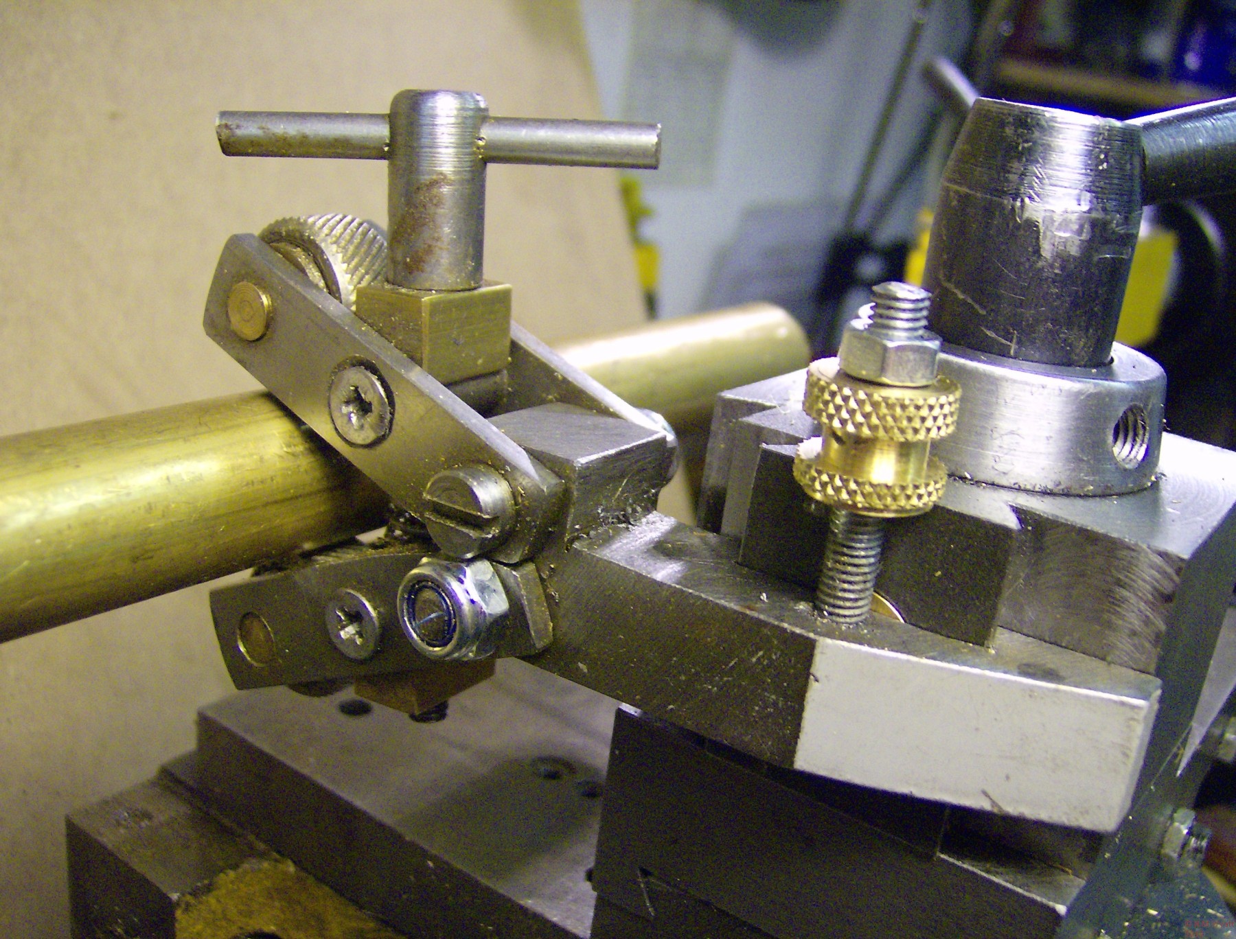
One of the very first workshop tools I made was an unsophisticated, but effective, clamp knurling tool. This was made with a bar that clamped in the four-way toolpost. I simply cut a dovetail in the bar and added a height setting stud. Although this hasn’t made the tool any prettier, it works well (I knurled along length of 1/2” diameter brass with this device to make the height setting buttons) and demonstrates the principle that any tool that can be fixed in the toolpost can potentially be modified in this way.
Simple scissors knurl modified to fit the QCTP
A Few More Thoughts…
Another idea is a holder reamed for an MT1 taper, a second is to make my keyway slotting tool fit the toolpost. Yet another is to modify my toolpost drill. Equally a toolpost grinder, multi-tool or any other device could be modified to fit on the dovetails. I’m sure there are many other possibilities.
Anyone who follows the discussions on the ME web forum will know how popular tangential toolholders are. I have made one of these for 1/4” HSS and it has proven very useful. I have made a QR toolholder version, and have included a concept drawing. This is something I have not seen elsewhere, but it seems blindingly obvious (perhaps I should have patented it even so). Note that as the toolbit can be adjusted separately for height, the holder needs to be set as low as possible, and maximise the amount of metal supporting the toolbit. This is why the lower part of the dovetailed body will need to be cut away.
As it is now so easy to adjust the height of your tools to be spot on with this new toolpost, the value of a height setting gauge becomes apparent! It also means there is no excuse not to swap tools as often as you need, rather than making do with the same tool for turning and facing, or accepting the finish from roughing tool. Hopefully, this means the standard of my turning will improve!
This article follows on from the first part on making the QCTP block.
You can download a free set of plans for the QCTP design with this link.

