If you find this website useful, please check out my books or visit my Amazon Author page. Or even Buy Me a Coffee!
Uncategorised
Uncategorised
My interests in music, publishing, design and photography have all come together in designing posters for musical events. Check out the examples of my designs below.
As well as just creating photos from pre-existing materials, I can source stock photos, special effects, create typographic and other logos. I have special AI software that can take low-resolution or fuzzy images such as videos or poor photos and make them usable. I am also able to do advanced editing, such as removing and replacing backgrounds or combining shots of different band members into a single image.
If you would like me to quote for designing a poster or logo for your band or event, or just to do some photo-editing, contact me:This email address is being protected from spambots. You need JavaScript enabled to view it.


- Details
- Category: Uncategorised
I’ve made a petition to the UK Government to restore funding for the Zoe App – will you sign it? I just need one or two more sponsors for the petition to go public. Thank you Neil Wyatt
Click this link to sign the petition: My petition: Restore funding for the Zoe Covid Tracking App and its development. Reverse the decision not to fund further work on the Zoe Covid Symptom Study and the widening of its work to look at a 'whole host of other health conditions', after carrying out a proper review of the risks of not funding the work and the potential benefits. The UKHSA has put £5M into supporting the Covid Symptom Study which uses the Zoe tracking application. The study has proven one of the most reliable and unbiased sources of data on the progress of the Covid pandemic. The technology promises huge potential for looking at a wide range of other health conditions, as well as being a potential tool to help minimise the impact of any future pandemic. The cost benefit ratio of further support for the Zoe tracking app is huge, and is the sort of action that only Government can take. Click this link to sign the petition: |
- Details
- Category: Uncategorised
I get asked this question quite often, and usually give a fairly brief summary of the process. Recently I wrote a longer response as a result of bing asked how I got from initial picture to this image of the Tadpoles Nebula IC410:

I used a Skywatcher 130P-DS Newtonian scope which is optimised for imaging, with a matching coma corrector to give sharp round stars across the image. Attached to the scope is an electronic focuser, a filter wheel with eight filters and a cooled mono camera (to give lower noise on very long exposures). There is also a smaller guidescope and camera attached to and roughly aligned with the main scope. This is all mounted on a tracking mount, controlled by a computer that also controls the cameras, filter wheel and focuser. As well as taking photos the computer deals with pointing the mount in the right place. It uses the guidescope and camera to take short (1s) exposures in which it tracks a star and uses this to correct the pointing of the scope in real time, typically with a precision around 1 arc-second.
The larger, cooled, camera is used to take multiple long exposures (typically several minutes, but many factors affect the optimum length, in this case it was mostly two minutes but could usefully have been two or four times as long).
Last year I collected a good set of data using a Hydrogen-alpha (Ha) filter which is a deep red light from ionised hydrogen and usually the strongest signal from nebulas like this. My filter has a 7nm bandwidth, so it suppresses pollution and reduces broadband light sources like stars.
A few nights ago I repeated this with oxygen (Oiii) (a blue-green light) and sulphur (Sii) (an even deeper red) filters.
The images from each layer (typically 20-30) are stacked automatically along with special frames to reduce 'dark noise' and distortions like vignetting (flat frames). As is typical all three layers needed to be 'stretched' (using curves, histogram etc.) to bring out faint details, denoised and given some contrast enhancement or sharpening. Some processes remove the stars then add them back in afterwards to highlight the nebula, but I tend not to use these often.
The Sii signal was very week, and needed a particularly strong stretch, I was surprised that it eventually revealed some quite delicate filamentary structure that sadly don't show strongly in the finished image.
I combined these using the 'Hubble' palette which maps the three layers in wavelength order Sii to red, Ha to yellow and Oii to blue. This starts with Ha mapped to green, but after balancing the image selective colour is used to push the green to yellow. As 0iii is weaker than Ha it often looks very turquoise and is usually shifted to be more blue. The Sii signal gives the Ha signal a browner tinge and can be best seen as a patch to the right of the nebula where the is little Ha.
The actual colour shifts are rather arbitrary as there is no 'scientific' right or wrong for the colour balance. Unstretched images can be used for photometric measurements, but are pretty uninspiring to look at, so just as when you process an earthly image you might choose to alter the saturation for a more pleasing result. In this case the objective is to make the colours reflect the relative distributions of different gasses in the nebula.
I finally improved the smoothness of the image by using the Ha layer as luminance, which remove the noise from the oxygen and sulphur data, but I'm hoping to get more data soon.
- Details
- Category: Uncategorised
The Veil Nebula is a huge supernova remnant in the constellation of Cygnus. It comprises several distinct deep sky objects such as NGC6960, NGC6992, NGC6993 with many twisting filaments glowing with hydrogen and oxygen light. Far bigger than the full Moon, this image is a big mosaic and may take some time to load. It comprises two panes taken using my home-made ED66 telescope which has a focal length of 400mm and a ZWO ASI1600MM PRO camera. I used an OVO field flattener which does not change the focal length. It is a narrowband image using ZWO 7nm filters mapped Ha - red, Sii - green, Oiii - blue.

- Details
- Category: Uncategorised
Roller and angular contact bearings suitable for mini lathes are available from Arc Euro Trade. These are made by Nachi, who apparently supply bearings for the legendary Japanese bullet trains. Unlike the standard ball bearings, which are shielded units, the roller bearings are open and in two parts – an outer race and the inner race with caged rollers attached. Try to overcome the temptation of taking the bearings out of their packaging before fitting them. If you do, keep them clean and do not run them ‘dry’.
See also: Parting Off on Mini Lathes and Bearing Choices
On the face of it replacing the existing ball bearings with taper roller bearings is straightforward - strip down the mandrel, remove the old bearings, lubricate and fit the new ones and re-assemble. In practice there are a few complications; the bearings are tight force fit in their housings and although the roller bearings are diametrically the same, they are longer which creates the need to make a number of adjustments.
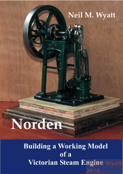
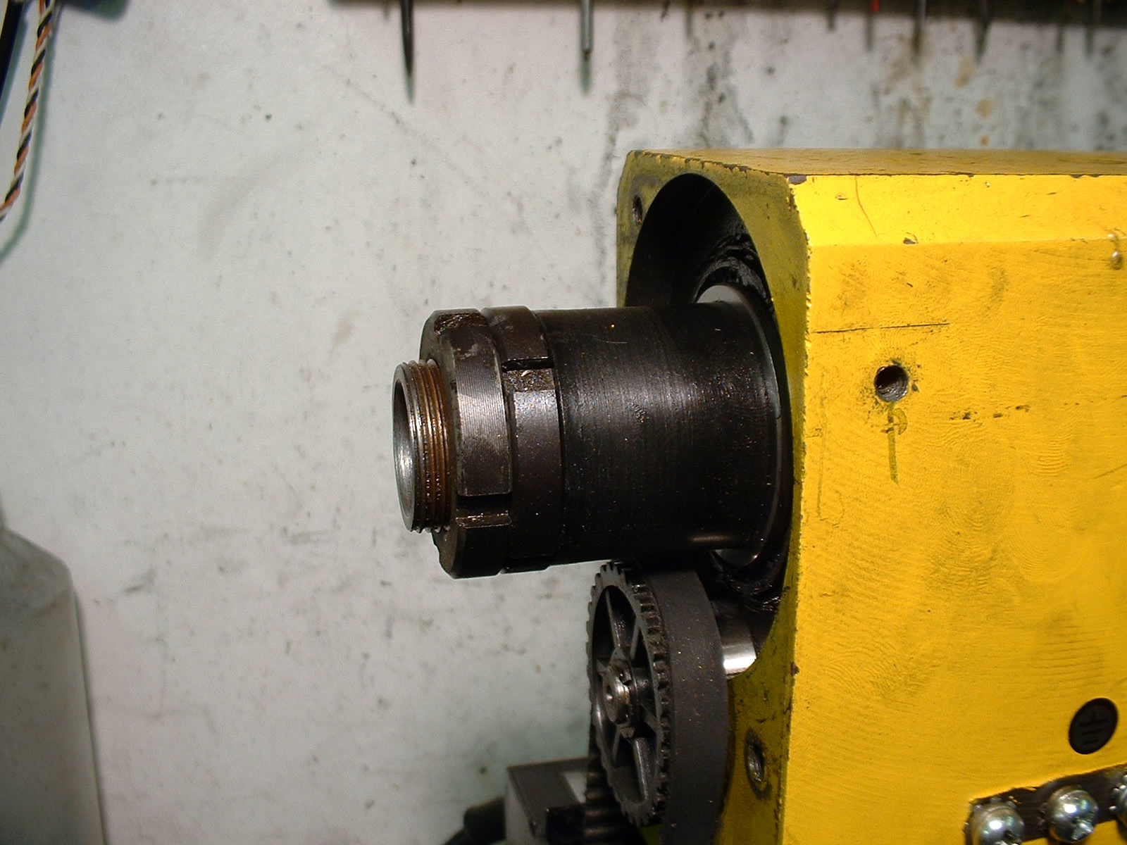
The end of the mandrel with locknuts, bull wheel and tumbler reverse plate removed.
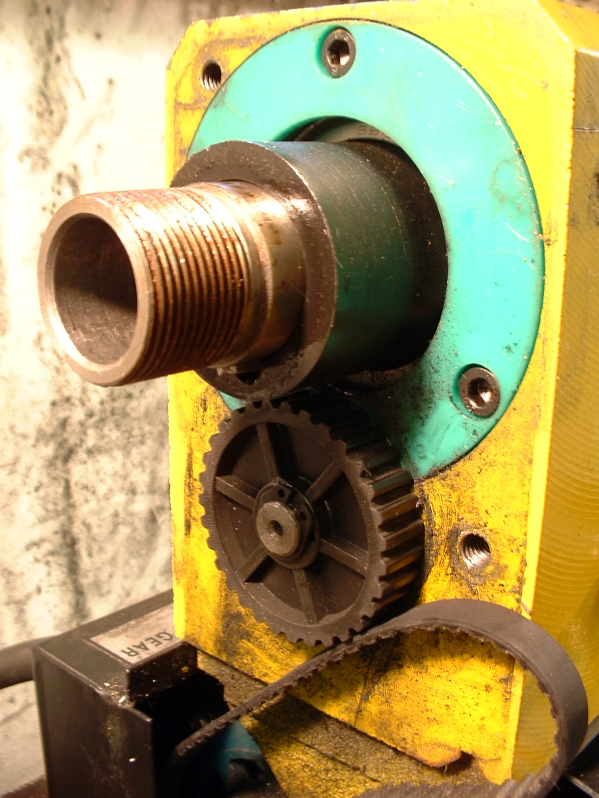
First of all unplug and isolate the lathe, and make sure you have plenty of space in which to work. The next operation is to strip the rear of the headstock. Remove the gear cover, any change gears that are in place, the drive belt and pulley, and finally the mounting plate for the tumbler reverse. It makes good sense to have a few small boxes in which to store the various components as they are removed, especially small items such as the drive pulley key. I suggest that you fully remove the control box, after noting how the various connections are arranged. In these days of camera phones I make a photographic record whenever I dismantle a novel device, it’s an excellent way of avoiding that ‘James Bond’ moment when you have to choose which pair of wires to reconnect!
Even in the simplest of cases a simple sketch or a digital photograph is always a help with ensuring that wiring is reconnected correctly and safely.
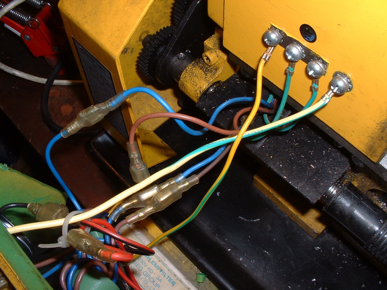
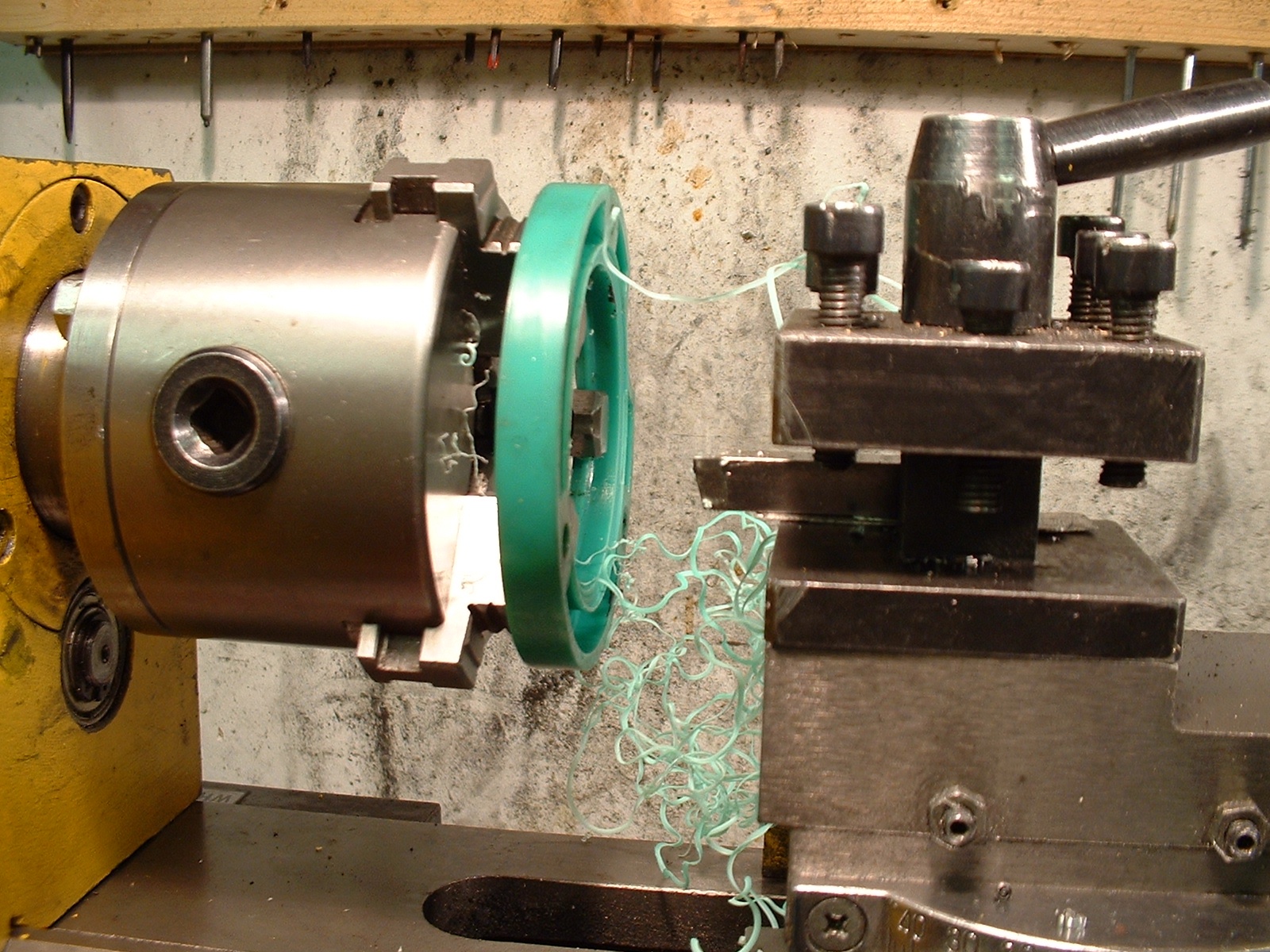
The locknuts at the end of the mandrel can now be removed using a c-spanner. You might have a suitable one in the form of the old pressed steel multi-spanners from the days when bicycles had built up bottom brackets. Otherwise it is possible to improvise one from steel strip and a suitable bolt – it should not be subject to huge loads. To free the locknuts you will need to immobilise the mandrel, and this can be done by bolting a bar to the front flange of the mandrel, or more simply by clamping a bar in a chuck. Please don’t write in about chuck abuse – the torque I needed to free the nuts was quite modest.
Removing locknuts.jpg – This method of removing or tightening the locknuts is fine as long as only modest force is required. If the nuts are jammed solid bolt a bar to a faceplate or the mandrel flange instead.
When the locknuts came free I was dismayed to find some apparent dampness and localised surface corrosion, but only on the thread and hidden faces of the locknuts. How this came about without affecting the rest of the lathe is beyond me, perhaps it happened when the lathe was stored in a cold garage for seven months? My remedy was to clean the thread and nuts and then treat them with Jenolite.
It is now possible to remove the 45-tooth bull wheel, wangle out its key and remove the long plastic spacer, followed by the plastic bearing shield which is held in place by three cap head screws. The two ends of the mandrel are covered by these plastic bearing shields. I found that I had to recess the inside of the bore of each shield by 2mm to clear the inner races. Unfortunately this only came to light once I had swapped the front bearing. I therefore had to recess the front shield by hand using a burr in a mini drill. An alternative is to recess the rear shield before removing the mandrel, swap it for the front one at the appropriate time, and recess the other shield when the mandrel is re-assembled. Unfortunately, to do this you will have to temporarily replace much of the drive gear. Whichever way you decide to proceed, the front shield will also need to be released before the mandrel is extracted. This is easily done by poking an Allen key through a hole in the mandrel flange.
The bearing shields can be recessed neatly in this way, however, a fair amount of assembly and reassembly is required if both are to be dealt with in this way.
To remove the mandrel you will need a suitable a puller. I used a length of 12mm studding, threaded through the mandrel bore, a section of angle iron and two 10mm bolts. The mandrel should come free under steady pressure, bringing the front race with it. In the unlikely event that the front race remains in the headstock, rather than staying in place on the mandrel, you will need to fabricate a longer puller as described on the Arc Euro Trade website.
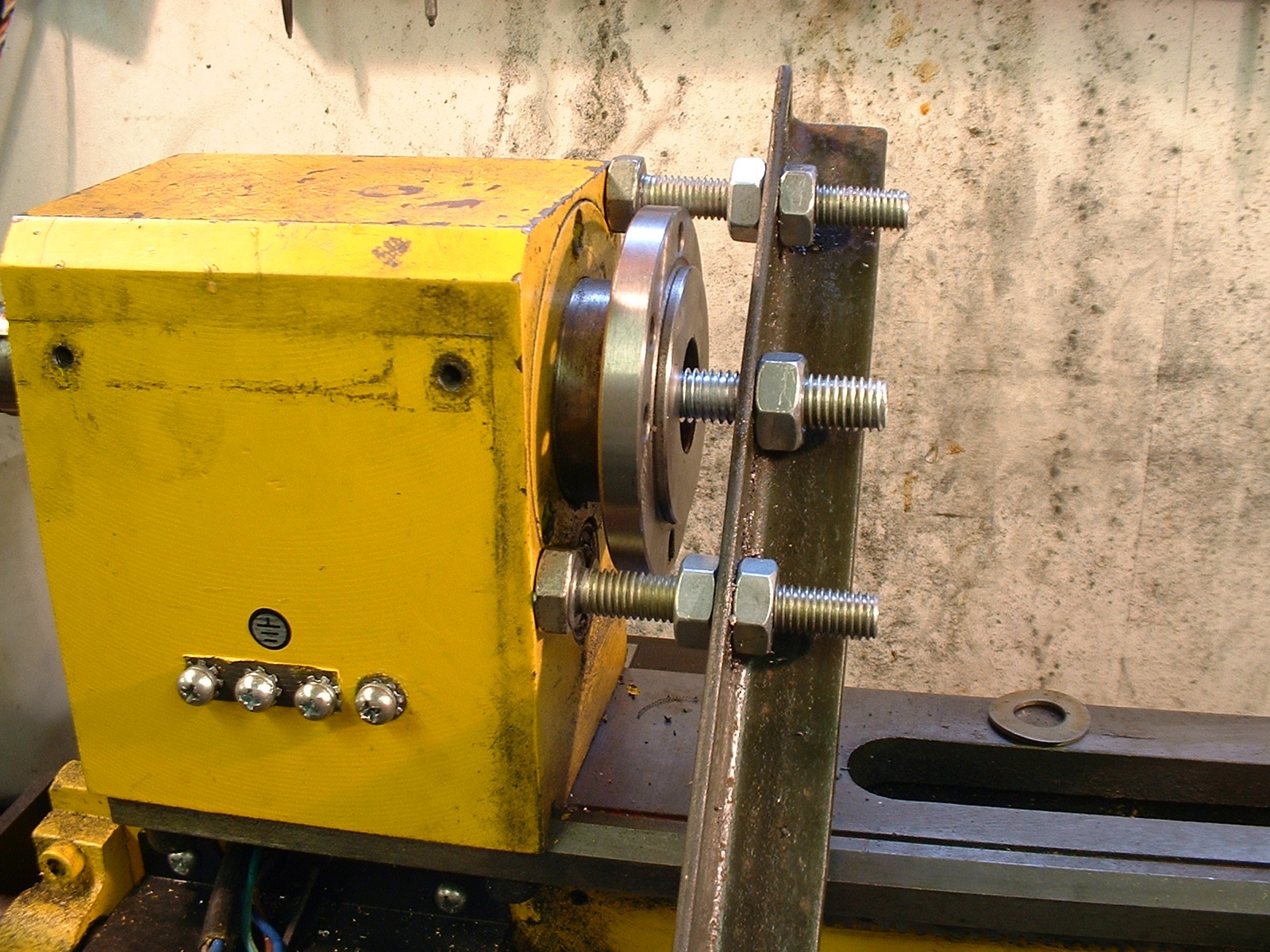
This fairly robust arrangement was needed to pull the mandrel. There is a nut and thick washer at the far end of the mandrel bore.
Once the mandrel comes free it will leave the gears and a spacer inside the headstock. Another spacer will probably come out with the mandrel, remove this and the long key (that engages the internal gears) and put them to one side.
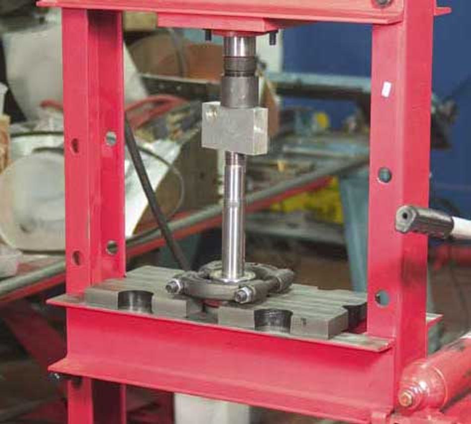
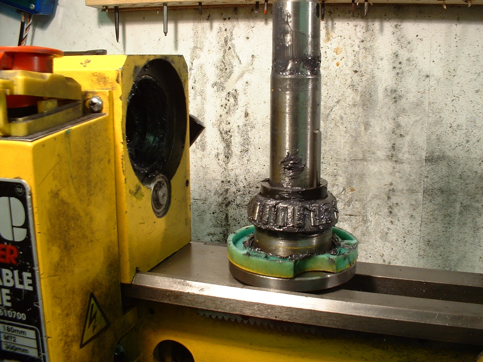
The ideal way to remove the front bearing is with a proper bearing splitter and an hydraulic press. (Photo courtesy Arc Euro Trade)
Lacking a press I had to resort to driving to remove the old bearing from the mandrel and replace it with the new inner race. I used two pieces of 3/8” square bar to make a support the old bearing as close to the mandrel as possible. After applying some light oil I drove the mandrel most of the way out, using an aluminium alloy drift to protect its end. Once the bearing was far enough up, I was able to use a proper Picador puller to finish the job. If I was to do this again I would probably either make extensions for the proper puller, or make a custom puller from scratch. With the bearing removed it is now possible to swap over the previously recessed bearing shield.
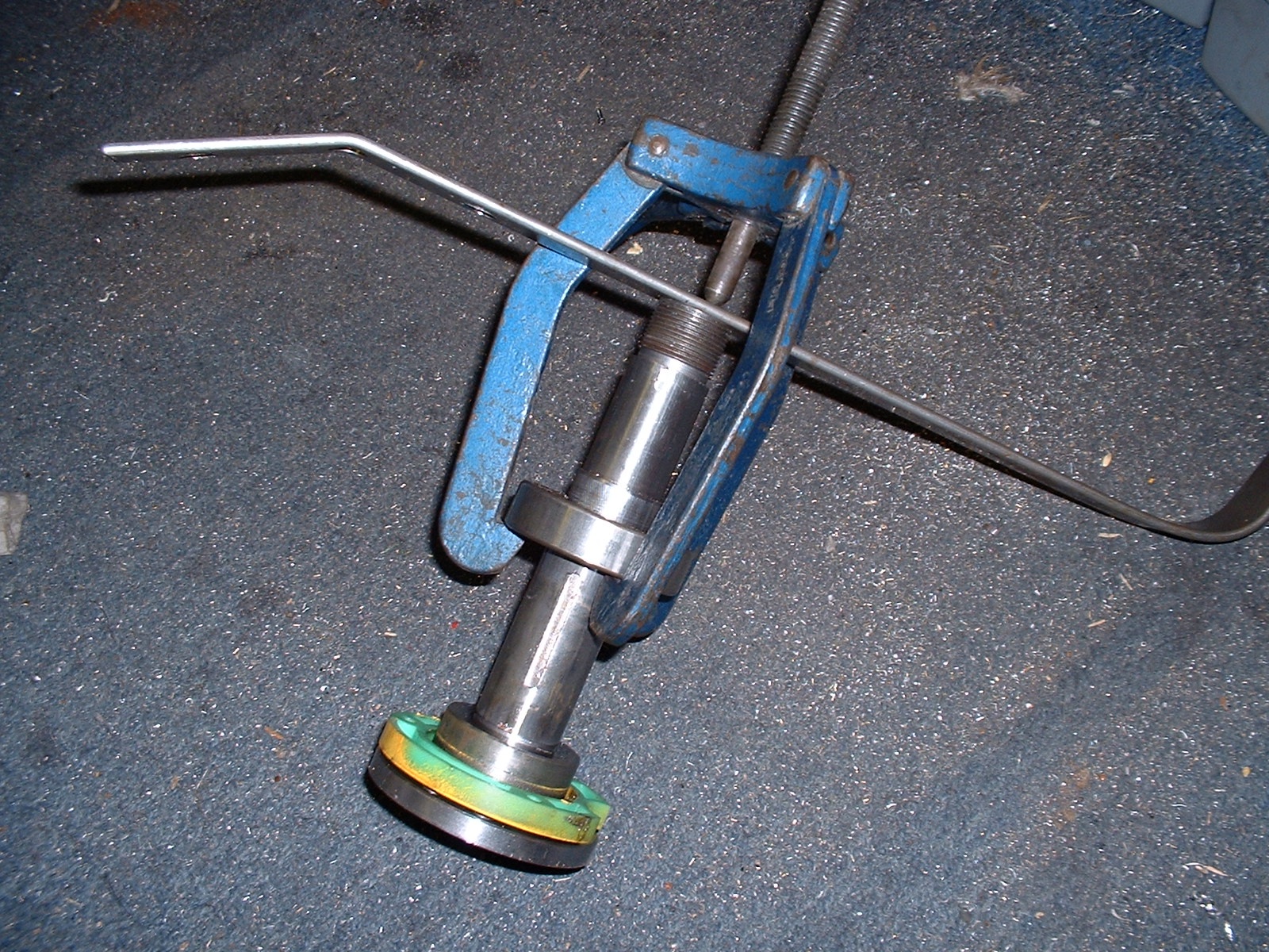
Unfortunately, the mandrel was too long for this Picador puller to be used the whole way.
I followed the advice on the Arc website and drove the new inner race into place using a tubular drift – a section of 30mm light alloy scaffold pole, probably the ideal material for the job. Whatever you use, make sure that it fits the inner race without overlapping the caged rollers. It is also important to protect the face of the mandrel by resting it on a block of softwood.
With the mandrel removed, I decided to remove the headstock from the lathe, partly out of curiosity, partly out of convenience. To do this requires the removal of the leadscrew, the motor and their respective guards. The headstock itself is retained by three 8mm cap screws. Once the headstock casting was removed the lathe bed beneath was covered in a layer of ‘plastic fluff’, the result of several year’s wear on the internal gears. Fortunately the gears are of generous dimensions and they did not appear badly worn. Even so it was obvious that it would be worth cleaning out the inside of the headstock and applying a generous amount of grease to all the moving parts before replacing it.
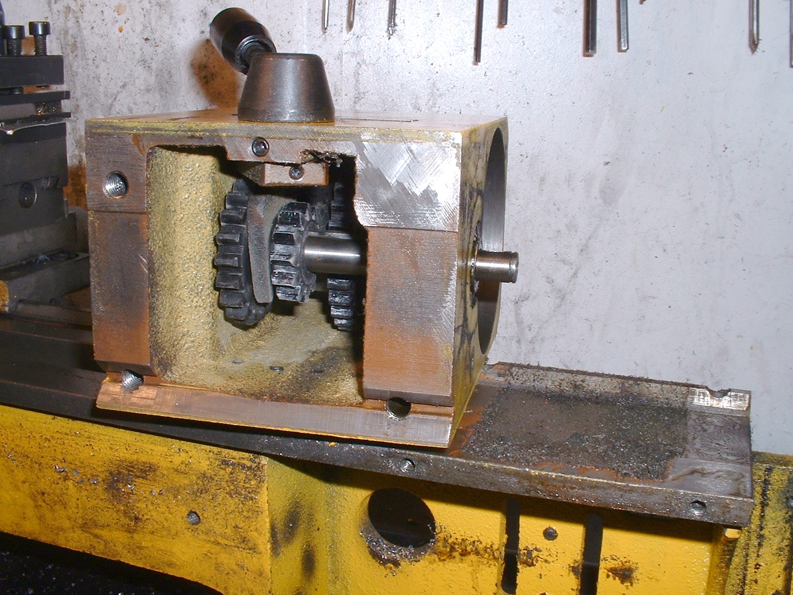
The inside of the headstock was devoid of any lubricant, the ‘dust’ on the lathe bed is the result of wear of the gears.
With the headstock removed it was a straightforward job to pull the rear bearing, using the home made puller and a short piece of 3/16” bar across the inside of the bearing. To fit the outer races to the headstock another suitable length of angle iron was required.
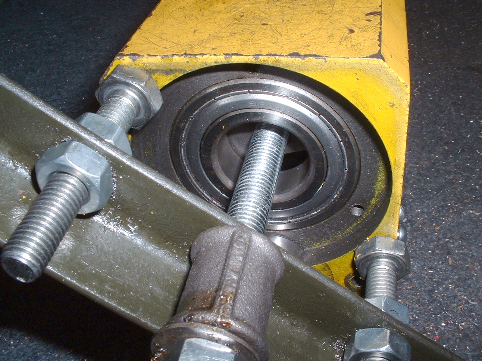
The rear bearing can be pulled in situ, but it is easier to carry out with the headstock removed from the lathe.
The front race went in with no trouble, but the rear one started to go in skewed an I had to adjust the puller. When I came to test the lathe it was apparent that one or both of these races was not completely pulled home, so watch for the puller contacting the headstock rather than the race.
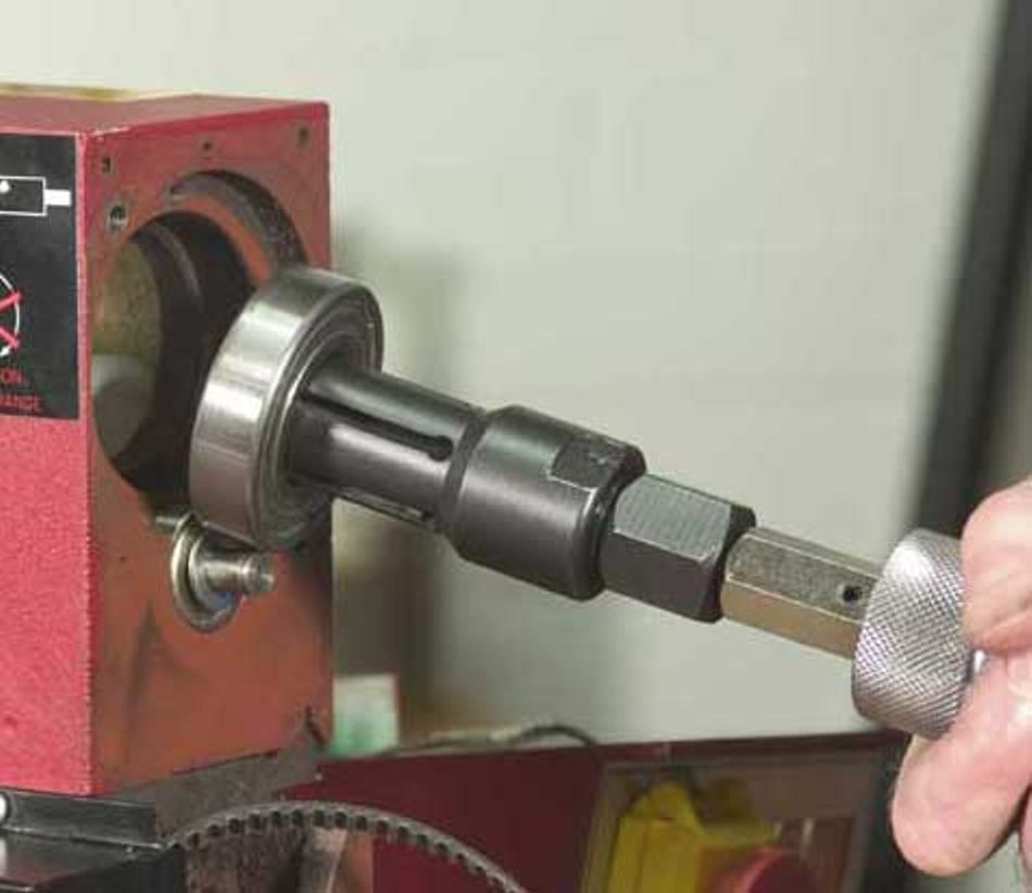
A blind puller with a sliding hammer can be used to remove the rear bearing. (Photo courtesy Arc Euro Trade)
Refitting the mandrel to the headstock is best done after refitting it to the bed of the lathe. Grease the internal gears and clean the bed before doing so. Fit the long key and one of the short spacers, then load the front bearing with suitable grease. I used a heavy duty moly-grease. Ideally you shoudl fill no more than 2/3 of the space in the bearing to avoid it slipping rather than rolling. Fortunately, there is plenty of space for excess grease to escape into the void of the headstock, so don’t worry to much about slightly overpacking the bearing.
The front bearing and its race liberally dosed with molybdenum sulphide grease.
The mandrel should slip easily into the headstock, threading into the internal gears and the second small spacer. Now load the rear bearing with grease and slip it onto the lightly oiled mandrel. You can now use the long spacer and one of the locknuts to draw it into place until there is no play, locking the mandrel with a bar in a chuck as before. Check the headstock gears engage properly and refit the tumbler reverse plate, motor, drive belt, leadscrew, control box and any other miscellaneous parts removed earlier. Check there are no obstructions and everything turns freely, then start up the lathe in low gear, gradually accelerating to full speed over a few minutes, then stop and check the spindle has not come loose. Repeat this procedure in high gear.
The bull wheel spacer before being shortened.
Now remove the locknut and thread on the bull wheel, it will be apparent that the bull wheel no longer lines up with the tumbler reverse. I had to shorten the spacer by 4mm, which I did in the lathe, relying on friction to hold the rear race in place against the light load. Once shortened I had to use a rat-tailed file to enlarge the notch in the spacer for the end of the bull-wheel key, before replacing the rear bearing shield, fitting the key and bull wheel. I then refitted both lock nuts and re-tightened the mandrel. Appropriate preload for a roller bearing this size and precision application is very small, of the order of zero to four thous. The pitch of the mandrel thread is 1.5mm or 60 thou so, once all shake has been removed with the first locknut, tighten it by no more than a further 24 degrees and lock it securely with the second nut.
The long bull wheel spacer was the only one I found it necessary to modify, shortening it by about 4mm.
Testing
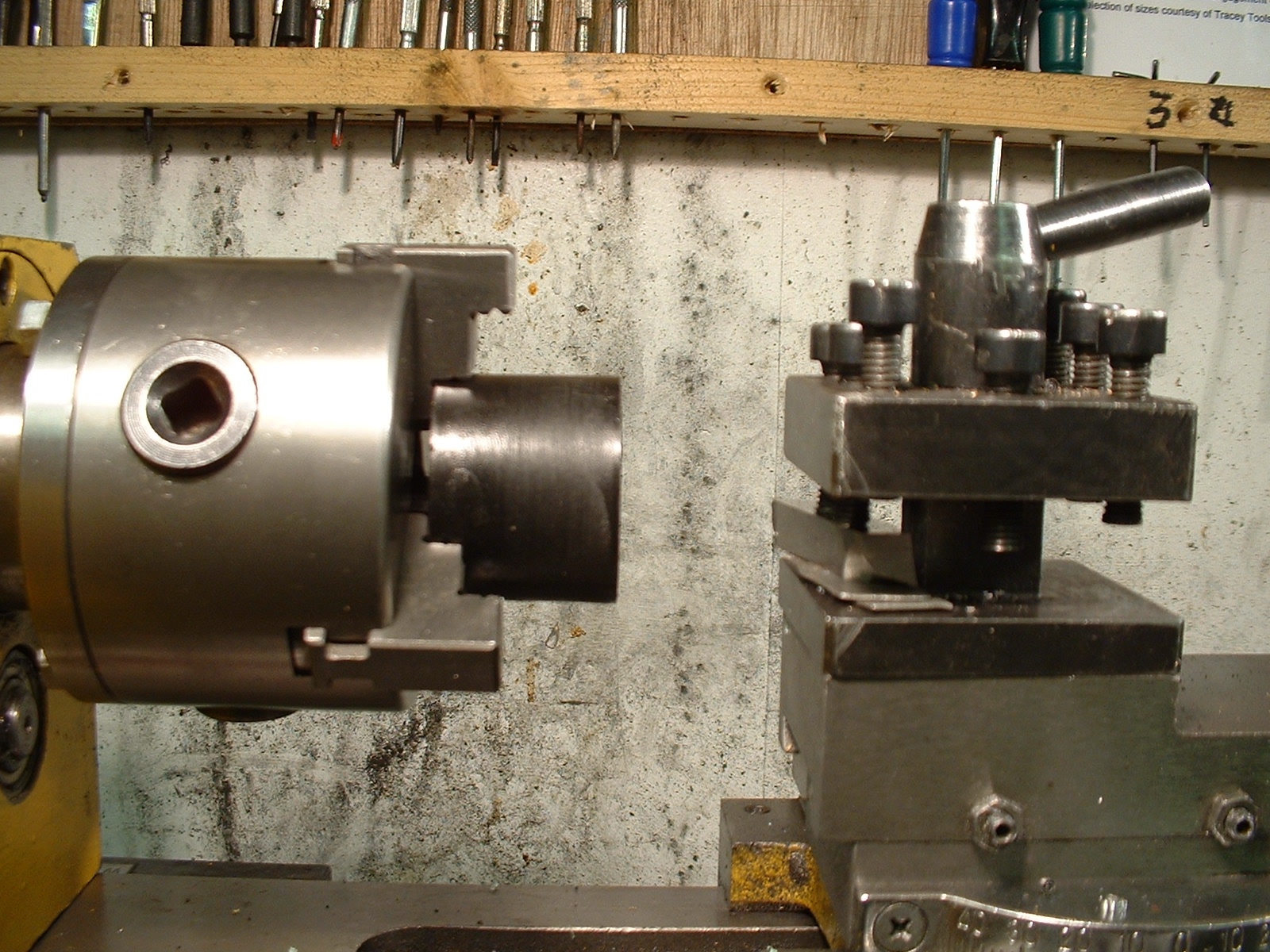
The first task I undertook was deliberately a light one, turning two 1 1/2” light alloy rings for a tailstock micrometer index. For the record the pitch of the tailstock leadscrew is 1.5mm, so 60 divisions for the index is 0.025mm, a close approximation to 1 thou per division. This did not go without incident, as one of the inner races shifted a little and I had to readjust the bearings. If the outer races snug in a bit further when you first use the lathe, it will become apparent as noise when first putting on a cut. Should this happen stop the lathe and retighten the bearing and no harm will be done.
Could I replicate George Thomas’ achivement of parting off 1 1/8” FCMS at 600rpm?
I have successfully parted off 1 1/2” mild steel to make the parts in photograph X and 1 1/8” alloy steel, to make the 0.025” thick disk. It took a little practice to develop the right technique. The tool was 3/32” wide with the cutting section 1/2” long, set dead on centre height. I got the best results starting at 220-250 rpm and then speeding up as the work progressed. It was essential to force the tool in positively at the start of the cut, then to maintain a steady feed rate, but being careful to watch for the work slowing down too much. Lubrication, using neat cutting oil on a small paintbrush helped keep the speed of the lathe up. Chatter was only evident if the cut was not aggressive enough. Feeding the tool in too fast did not cause dig-in, instead the ‘motor slowed and the fused blowed’. This suggests that the limiting factor is now the motor power, not the rigidity of the lathe.
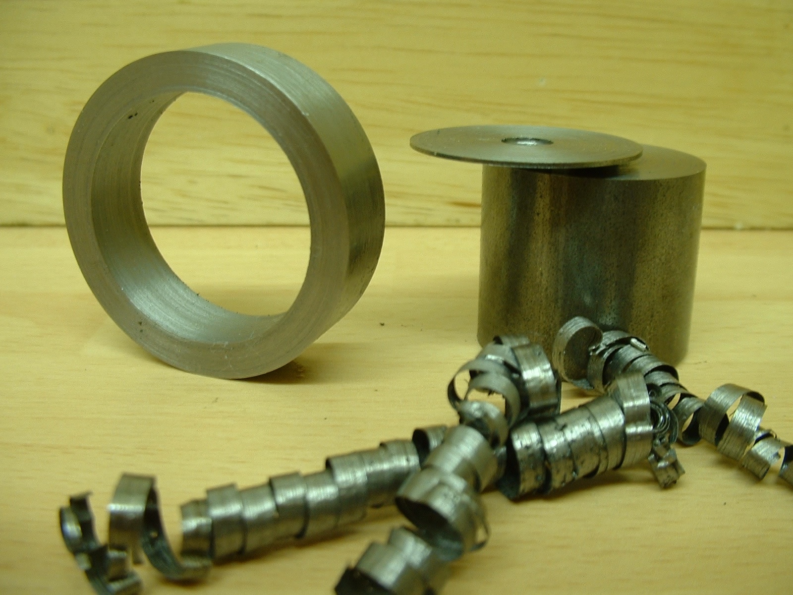
Examples of items parted off with the modified lathe. The disc is 0.025” thick, and could easily have been made thinner. The swarf is 3/32” wide by about 0.004” thick, a flatter topped tool would have made less tightly wound swarf.
A final and more extreme test was to cut a 3/32” groove in 2” mild steel. Running the lathe at about 310 rpm I set up my digital camera to video the event. Remarkably the tool went in like a knife into butter – no chatter and short coils of swarf flying out like chips from brass!
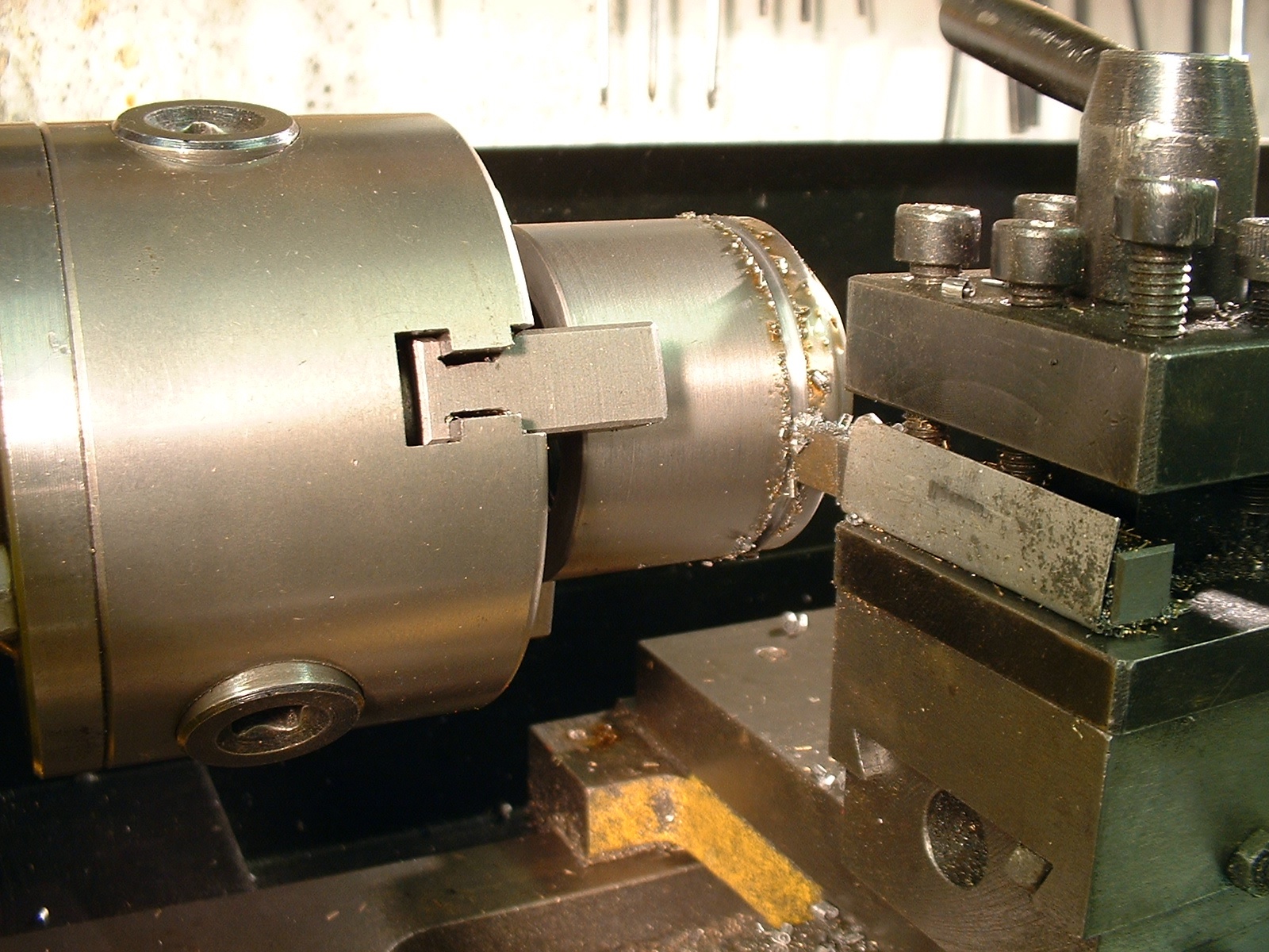
Parting off.jpg – After cutting a 3/32” wide groove in 2” diameter mild steel. The lathe was run at over 300 rpm, and no chatter was experienced.
I had not expected such a dramatic improvement in parting off, particularly from the point of view of being able to speed up and increase the depth of cut so markedly. I certainly did not expect any other changes, but there were two. The first came to light when running in the new bearings – the reduced friction meant the lathe ran far more smoothly at low speed – it would now turn at just 4 rpm without stutter. This could be very useful if I decide to mill or grind helical threads in the future.
The second and welcome change was the improvement in surface finish on tougher materials. I was not expecting this, yet there was a noticeable improvement in the surface finish when turning both mild and medium carbon steels. So far I have seen none of the ripples or waviness that troubled LBSC over eighty years ago. I wonder if his problem was poor bearing quality or just too much preload?
I did have two reservations about the change. One is the apparent 4mm of increased mandrel overhang, however because the new bearings have a linear contact patch instead of a point, the new bearings actually support the mandrel with /less/ overhang. The second is that the new bearings are unshielded. Provided the plastic shield are undamaged and the bearings well packed with grease this ought not to be an issue. Assuming normal levels of use it would be a good idea to draw the mandrel and inspect and repack the bearings every couple of years to ensure long life.
I had considered changing the bearings a last resort to rescue a worn or otherwise unsatisfactory machine, would I be able to detect any difference? In practice, for a day’s effort and at very modest cost, the results really surprised me. Even with a lathe that appears to be performing well with the standard ball bearings, consider changing to roller bearings and taking full advantage of the basic precision and rigidity of the mini lathe design.
See also: Parting Off on Mini Lathes and Bearing Choices
- Details
- Category: Uncategorised
Page 1 of 2
- You are here:
-
Home

-
Model Engineering
- Uncategorised